audi Workshop Repair Guides

Audi Workshop Service and Repair Manuals

Checking cruise control system - TDI engines > < Cruise control system (CCS) self-diagnosis
Checking cruise control system - petrol engines with electronic throttle
Sequence of operations
l  Vehicle diagnostic, testing and information system -VAS 5051B- connected and vehicle self-diagnosis selected → Chapter
l  Engine idling.
   
Display on -VAS 5051B-:
–  From list -1- select vehicle system “01 - Engine electronics”.
–  Wait until next display appears.
  A01-0120
Display on -VAS 5051B-:
1 - Identification of engine control unit
2 - Control unit identification of immobilizer
–  Touch key.
  A01-0121
Display on -VAS 5051B-:
–  From list -1-, select function “08 - Reading measured value block”.
  A01-0122
Display on -VAS 5051B-:
–  On the keypad -2-, touch keys 66 for “Display group 066” and confirm the entry by touching the Q key.
  A01-0130
Display on -VAS 5051B-:
–  Check display in zone -2-.
  A01-0187
Test conditionDisplay zone 2 with 4-digit display
CCS released 1)“1”000
Brake pedal pressed10“1”“1”
Clutch pedal pressed1“1”00
l  1) If value “0” is displayed: Activate cruise control system → Chapter.

   
Test conditionDisplay zone 2 with 8-digit display
CCS released 1)0000“1”000
Brake pedal pressed000010“1”“1”
Clutch pedal pressed00001“1”00
l  1) If value “0” is displayed: Activate cruise control system → Chapter.

   
–  Check display in zone -4-.
  A23-0039
Test conditionDisplay zone 4 with 4-digit display
Switch -B- set to “OFF”, latched0000
Switch -B- set to “ON”00“1”“1”
Switch -A- pressed “FIX”0“1”11
Switch -B- set to “ACTIVATION”“1”011
Switch -B- set to “OFF”, before latching point (deceleration)00“0”1

   
Test conditionDisplay zone 4 with 8-digit display
Switch -B- set to “OFF”, latched00000000
Switch -B- set to “ON”000000“1”“1”
Switch A pressed “FIX”00000“1”11
Switch -B- set to “ACTIVATION”0000“1”011
Switch -B- set to “OFF”, before latching point (deceleration)000000“0”1

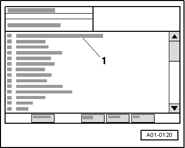
–  Terminate function “08 - Reading measured value block” by touching key.
If readings do not match specifications:
Checking wiring
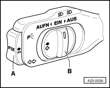
–  Unplug the connector at the cruise control system switch → Rep. Gr.94.
–  Connect the 121-pin adapter cable -V.A.G 1598/31- (test box) to the unplugged multi-pin connectors of the engine control unit → Rep. Gr.24.
  Note
t  Use is always to be made for connecting measuring instruments (e.g. voltage tester -V.A.G 1527B-, portable multimeter -V.A.G 1526C-) of the adapter set -V.A.G 1594C-.
t  The contact numbers of the multi-pin connectors coincide with the socket numbers of the adapter cable -V.A.G 1598/31- (test box).
  Caution
To avoid damaging electronic components, select the appropriate measuring range before connecting the test leads and heed the test conditions.
–  Check for open circuit and short to earth or positive in the wiring → Current flow diagrams, Electrical fault finding and Fitting locations.
–  Repair wiring if necessary.
   

Checking cruise control system - TDI engines > < Cruise control system (CCS) self-diagnosis