audi Workshop Repair Guides

Audi Workshop Service and Repair Manuals

Connections to interface for navigation -R94 > < Structure of Navigation System II -D with BOSE-sound system -Avant-
Radio, Telephone and Navigation System
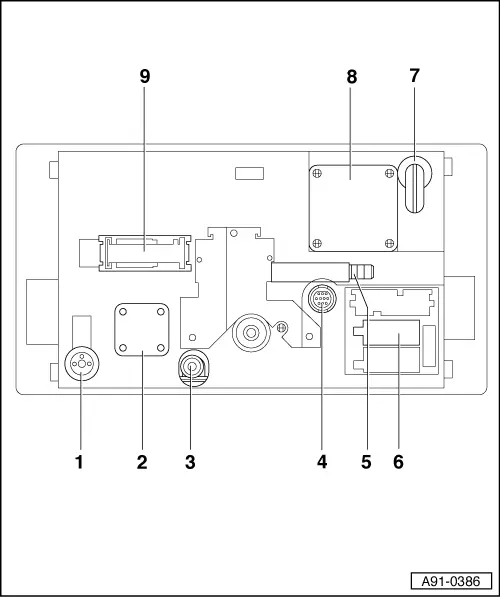
Navigation system II-D (Navigation system plus) (as of CW 48/99)
Connectors on rear of operating electronics control unit, navigation -J402
 
A91-0386
  • Radio aerial connection: Connection socket for radio aerial
  • Fan for cooling system
  • IF wiring
  • Video connection; 11-pin connector for connection of TV tuner in rear left storage compartment in luggage compartment
  • Earth connection
  • Radio connection: 36-pin connection block with three multi-pin connectors and a fuse
 
A91-0386
  • GPS aerial connection; connection socket for the navigation system aerial on the luggage compartment lid
  • Fan for cooling system
  • Navigation system connection: 26-pin connector for navigation system pickups

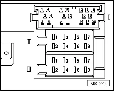
Contact assignment of multi-pin connectors for operating electronics/navigation system control unit

Note:

Connector contacts not listed have not been assigned.

 
A90-0014

→ Radio connection:

Multi-pin connector I, 20-pin

  •     1 -    Line output for rear left loudspeaker
  •     2 -    Line output for rear right loudspeaker
  •     3 -    Line output, earth
  •     4 -    Line output for front left loudspeaker
  •     5 -    Line output for front right loudspeaker
  •     6 -    Switched positive for BOSE power amplifier
  •     7 -    Telephone AF +
  •     11 -    Remote control (from control unit for multi-functional steering wheel)
 
A90-0014
  •     12 -    Telephone AF -
  •     13 -    CD DATA IN
  •     14 -    CD DATA OUT
  •     15 -    CD CLOCK
  •     16 -    Supply voltage to CD changer
  •     17 -    Control wire to CD changer
  •     18 -    Earth signal wire (CD-NF-earth)
  •     19 -    Signal wire for left channel (CD AF left)
  •     20 -    Signal wire for right channel (CD AF right)

 
A90-0014

→ Radio connection:

Multi-pin connector II, 8-pin, brown

  •     3 -    Loudspeaker +, front right
  •     4 -    Loudspeaker -, front right
  •     5 -    Loudspeaker +, front left (for BOSE sound system in conjunction with telephone hands-free loudspeaker +)
  •     6 -    Loudspeaker -, front left (for BOSE sound system in conjunction with telephone hands-free loudspeaker -)
 
A90-0014

→ Radio connection:

Multi-pin connector III, 8-pin, black

  •     1 -    Gala (speed signal)
  •     2 -    Telephone mute
  •     3 -    K wire (self-diagnosis)
  •     4 -    Connection for switching on and off via ignition key (S contact)
  •     5 -    Safe (constant positive from battery; anti-theft protection)
  •     6 -    Lighting dimmer (terminal 58s)
  •     7 -    Supply voltage (terminal 30)
  •     8 -    Earth (terminal 31)
 
A91-0113

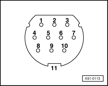
→ Video connection (RGB video input)

Multi-pin connector, 11-pin

  •     1 -    AF earth
  •     2 -    AF left
  •     3 -    AF right
  •     4 -    Video signal (CSYNC)
  •     5 -    Video earth
  •     6 -    PAL/NTSC
  •     7 -    V switch
  •     8 -    Input B
  •     9 -    Input G
  •     10 -    Input R
  •     11 -    Screen earth
 
A91-0112

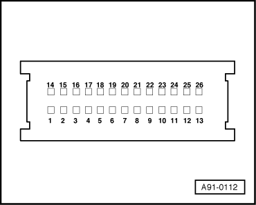
→ Navigation system connection

Multi-pin connector, 26-pin

  •     4 -    Terminal 15
  •     5 -    Speed sensor input, left (ABS)
  •     13 -    CAN bus high
  •     14 -    Switched positive (power aerial)
  •     17 -    Reversing light switch
  •     18 -    Speed sensor input, right (ABS)
  •     26 -    CAN bus low

Connections to interface for navigation -R94 > < Structure of Navigation System II -D with BOSE-sound system -Avant-