audi Workshop Repair Guides

Audi Workshop Service and Repair Manuals

Removing and installing "chorus and concert" radio unit > < Structure of radio systems (vehicles from model year 1998)
Radio, Telephone and Navigation System
Radio Systems
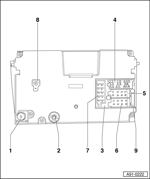
Connectors on rear of "symphony" radio
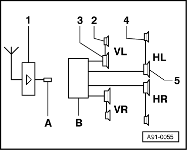
 
A91-0222
  • Aerial connection sockets for radio (high frequency wire)
  • Fan for cooling system
  • Radio connector block
  • Multipin connector I, 20-pin, consists of
    • ◆ Partial connector, 6-pin, yellow
    • ◆ Partial connector, 6-pin, green
    • ◆ Partial connector, 8-pin, blue
  • Multi-pin connector II, 8-pin, brown
  • Multi-pin connector III, 8-pin, black
  • Multi-pin connector IV, 10-pin, red
  • ATW earth
  • Radio fuse in radio

Radio preparation

 
A91-0055
  •     A -    → Aerial cable
  •     B -    Connector II (8-pin) and connector III (8-pin)
  •     1 -    Rear window aerial with aerial amplifier -Saloon-
  •      -    Roof aerial with amplifier -Avant-
  •     2 -    Mid-range/treble loudspeaker (installed in front upper door trim)
  •     3 -    Bass loudspeaker installed in front lower door trim
  •     4 -    Mid-range/treble loudspeaker installed in rear upper door trim
  •     5 -    Bass loudspeaker installed in rear lower door trim

Contact assignment for multi-pin connectors II and III

Note:

Pin assignments which are not listed are vacant or not assigned.

 
A91-0036

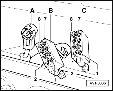
→ Multi-pin connector II, 8-pin, brown -C-

  •     1 -    Loudspeaker (+), rear right
  •     2 -    Loudspeaker (-), rear right
  •     3 -    Loudspeaker (+), front right
  •     4 -    Loudspeaker (-), front right
  •     5 -    Loudspeaker (+), front left
  •     6 -    Loudspeaker (-), front left
  •     7 -    Loudspeaker (+), rear left
  •     8 -    Loudspeaker (-), rear left

Multi-pin connector III, 8-pin, black -B-

  •     1 -    Gala (speed signal)
  •     2 -    AF mute (telephone system)
  •     3 -    Battery + (terminal 30)
  •     4 -    Terminal 86s - connection for switching on and off via ignition key (S contact)
  •     5 -    Control positive for aerial amplifier
  •     6 -    Illumination (terminal 58d)
  •     7 -    Battery + (terminal 30)
  •     8 -    Earth (terminal 31)

Connecting radio during preparation for radio installation

  • ‒ Carefully lever cover out of centre console and remove.
 
A91-0036
  • ‒ → Connect aerial cable -A-.
  • ‒ Connect the black connector -B- and the brown connector -C- to the radio.
  • ‒ Carefully insert radio in dash panel and engage in mounting frame.
  • ‒ If applicable, activate anti-theft coding according to the radio operating instructions.

Removing and installing "chorus and concert" radio unit > < Structure of radio systems (vehicles from model year 1998)