Note | t
| At absolute pressure, “0 bar” corresponds to an absolute vacuum. Normal ambient pressure thus corresponds to roughly “ 1 bar ” absolute. On the scales of most pressure gauges, “0 bar” corresponds to an absolute pressure of one bar (can be seen from “-1” mark below “0”). |
| t
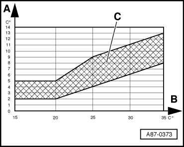
| The pressure in the refrigerant circuit is governed by ambient temperature. Due to heat emitted by components (e.g. radiator), the pressure displayed with warm engine is slightly higher than that indicated for the relevant ambient temperature. |
| t
| If the pressure displayed is lower than that given in the table, check measured value of high-pressure sender -G65- → Chapter“Reading measured value block” and → Chapter“Electrical checks, test step 5”. If no fault is found at the high-pressure sender, there is not enough refrigerant in the circuit and the vehicle must be taken to a specialist air conditioner workshop. |
| If pressure in refrigerant circuit is OK: |
| –
| Switch on compressor by selecting “Auto” mode on operating and display unit, Climatronic control unit -J255- (lamp in Econ button does not light). |
| –
| Set “Lo” temperature (for driver's and passenger's side) on operating and display unit, Climatronic control unit -J255-. |
| –
| Set air outflow direction on operating and display unit, Climatronic control unit -J255- to “dash panel vents”. |
| –
| In “Reading measured value block” function → Chapter, select display group “001” → Chapter. |
| –
| Check display in display zones: |
| –
| Display zone “2” shows a duty cycle of greater than 30% (actuation of air conditioning system compressor regulating valve -N280-, compressor is switched on). |
| –
| Display zone “1” shows a current of greater than 0.3 A (current flowing via air conditioning system compressor regulating valve -N280-, compressor is switched on). |
| –
| Pressure displayed in zone “4” rises above value when compressor is switched off. |
Note | t
| The air conditioning system compressor regulating valve -N280- is actuated by the operating and display unit, Climatronic control unit -J255- such that the temperature of the air downstream of the evaporator reaches the specified value (approx. 2 to 5 °C). After starting the vehicle, a value greater than 75 % (0.55A) is displayed depending on measured temperature, engine speed and electrical system voltage. As soon as the temperature measured by the evaporator outflow temperature sender -G263- approaches the specified value, actuation is cancelled and compressor output thus reduced. |
| t
| Under certain operating conditions, residual moisture in the coolant circuit may lead to the formation of ice at the compressor regulating valve. Such ice formation impairs compressor control, the evaporator is cooled excessively and ices up. Icing-up of the evaporator may give rise to the following problems: |
| t
| - Repeated or sporadic failure of air conditioner (no cooling/heat output) after a long journey; air conditioner functions properly again after a short delay following engine shutoff. |
| t
| - Misting up of windows on inside after a long journey; windows are initially not cleared even by pressing “Defrost” button; air conditioner functions properly again after a short delay following engine shutoff. |
| t
| - Check measured value of evaporator outflow temperature sender -G263- → Chapter“Reading measured value block”, display group “010”. |
| t
| If the sender measured value is too high under usage conditions described by customer (greater than e.g. 10 °C although air conditioner is functioning properly), check evaporator outflow temperature sender -G263- (incorrect measured value can cause evaporator to ice up). |
| t
| - If the sender measured value is too low under usage conditions described by customer (colder than 0 °C for lengthy period at ambient temperature above 0 °C) although the air conditioning system compressor regulating valve -N280- is not currently being actuated, the vehicle is to be taken to a specialist air conditioner workshop. |
| t
| - Check refrigerant pipe between evaporator and reservoir (thick pipe, low-pressure end) with engine running. If this pipe is severely iced up when the problem occurs (a thin layer of ice is permissible), this is also an indication that the temperature in the evaporator is too low. |
| t
| - Make the specialist air conditioner workshop aware of any problem encountered. The necessary work can only be performed by such specialists (draining of refrigerant circuit, replacement of reservoir and subsequent evacuation of refrigerant circuit for at least 3 hours). |
| t
| - If display zone “1” shows no or insufficient current, check actuation of air conditioning system compressor regulating valve -N280- → Chapter“Electrical checks, test step 6”. |
| t
| - If the pressure indicated in display zone “4” does not change and compressor actuation is OK (display zones “1” and “2”), there is a fault in the refrigerant circuit and the vehicle is to be taken to a specialist air conditioner workshop. |
| –
| Press recirculated-air flap button (“recirculated-air mode” symbol in button lights). |
| –
| Set engine speed to 2000 rpm (start of time measurement). |
| –
| In “Reading measured value block” function → Chapter, select display group “010” → Chapter. |
|
|
|