audi Workshop Repair Guides

Audi Workshop Service and Repair Manuals

Checking actuation of heated windscreen Z2 > < Checking electric supplementary heater
Checking
Checking
–  Measurement of the auxiliary heater elements -Z35- involves removing the driver's storage compartment → General body repairs, interior; Rep. Gr.68.
   
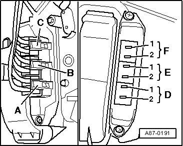
–  Unplug connectors -A-, -B- and -C- from auxiliary heater elements -Z35-.
–  Check the individual heater elements. The measured value between the individual contacts (from contact “D 1” to contact “F 2”) is a function of temperature and is between 0.2 and 5  Ω.
  Note
t  The auxiliary heater element -Z35- consists of several layers of resistor elements which together attain a heat output of approx. 1000 W (with actuation of all 3 inputs). These resistor elements have a positive temperature coefficient (the resistance increases with temperature and the current input decreases).
t  The resistor-type heater elements are actuated individually. However, as they are all interconnected in the auxiliary heater element -Z35-, the current flows via the earth connection offering the least resistance.
t  The auxiliary heater element -Z35- is designed such that, on activation, it is not possible for a current in excess of 35 A to flow via any of the contacts (resistance increases immediately following activation and current decreases).
t  To attain the maximum heat output of approx. 1000 W (3 x 333 W), the temperature of the resistor-type heater elements must be low and sufficient current must be supplied by the alternator -C-.
t  As resistances of less than 10 ohms cannot be measured with sufficient accuracy using workshop equipment, it is not possible to establish a short circuit in the auxiliary heater element -Z35-.
–  Actuate the low heat output relay -J359- and the high heat output relay -J360- by way of the “final control diagnosis” function of the relevant engine control unit and in doing so measure the voltage between the two contacts of the connectors -A-, -B- and -C- → "Guided fault-finding" function of vehicle diagnostic, testing and information system VAS 5051, → Diesel direct injection and glow plug system; Rep. Gr.01 and → Current flow diagrams, Electrical fault finding and Fitting locations
  Note
  A87-0191
t  The engine control unit actuates the auxiliary heater element -Z35- in 3 stages. For this purpose, the contacts in the connectors -A-, -B- and -C- are supplied with voltage as follows (the corresponding wiring can be seen from the relevant current flow diagram → Current flow diagrams, Electrical fault finding and Fitting locations).
t  For stage “1”, voltage is switched by the low heat output relay -J359- to one connector.
t  For stage “2”, stage “1” is deactivated and voltage switched via the high heat output relay -J360- to the other two connectors.
t  For stage “3”, stage “1” is switched in in addition to stage “2”. → "Guided fault-finding" function of vehicle diagnostic, testing and information system VAS 5051, → Diesel direct injection and glow plug system; Rep. Gr.01 → Current flow diagrams, Electrical fault finding and Fitting locations
t  The engine control unit constantly monitors the capacity utilisation of the alternator -C-. If this remains below a certain limit, the next stage is switched in. Switching back a stage is effected if a specified limit is exceeded.
  A87-0191

Checking actuation of heated windscreen Z2 > < Checking electric supplementary heater