-
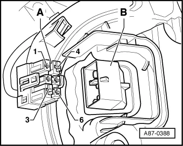
◆ → On vehicles with sun roof with solar cells, voltage generated by solar cells of sun roof is applied to contact 6 of connector when sun roof is closed.
-
◆ Fresh-air blower control unit -J126 is constantly monitored by -E87 (heating). Any faults occurring are stored in fault memory. Instantaneous status of fresh-air blower -V2 is displayed in measured value block=>Reading measured value block, Page 01-114 (display group 018).
Wiring to fresh-air blower control unit -J126
|
|
|---|
|
VAS 5051, measurement mode: Multimeter, resistance measurement (20 kω/ 200 kω)
▪ Adapter cables V.A.G 1598/11 and V.A.G 1598/12 connected
|
|
Test step
|
V.A.G 1598 A socket
|
Testing of
|
▪ Test conditions
- Additional work
|
Specification
|
Remedies if specification not attained
|
|
3.2
|
5
+
Connector to -J126 contact 2
|
Wiring between -E87 (heating) and fresh-air blower control unit -J126
|
|
- Less than 5 ω
|
- Locate and eliminate open circuit in wiring between -J126 and -E87 (heating)
|
|
3.3
|
6
+
Connector to -J126 contact 1
|
|
|
- Less than 5 ω
|
- Locate and eliminate open circuit in wiring between -J126 and -E87 (heating)
|
|
|
|---|
|
VAS 5051, measurement mode: Multimeter, voltage measurement (20 V DC)
▪ Adapter cable V.A.G 1598/12 connected
|
|
Test step
|
V.A.G 1598 A socket
|
Testing of
|
▪ Test conditions
- Additional work
|
Specification
|
Remedies if specification not attained
|
|
3.4
|
5
+
13
|
Wiring between -E87 (heating) and fresh-air blower control unit -J126
|
▪ Ignition on
▪ Connector of fresh-air blower control unit -J126 unplugged
|
- Less than 1 V
|
- Use current flow diagram to locate and eliminate short to positive
|
|
3.5
|
6
+
13
|
|
|
- Less than 1 V
|
- Use current flow diagram to locate and eliminate short to positive
|
|
3.6
|
5
+
12
|
|
|
- Less than 1 V
|
- Use current flow diagram to locate and eliminate short to earth
|
|
3.7
|
6
+
12
|
|
|
- Less than 1 V
|
- Use current flow diagram to locate and eliminate short to earth
|
Test step 4:
Heating system control motors and corresponding potentiometers
Notes:
-
◆ Resistance value of potentiometers in control motors (Specification: 3.6 ... 5.7 kωbetween contacts 1 and 3) can only be measured directly at control motor (parallel connection).
-
◆ Resistance value of potentiometers in control motors (between contacts 1 and 2 as well as 3 and 2) is governed by position of control motorand is only to be measured with control motorinstalled. Upper specification is not attained in test steps 4.1 and 4.2 (to attain upper specification, all connectors would have to be unplugged from other control motors during measurement - parallel connection).
-
◆ If -E87 (heating) detects fault "Potentiometer short to earth" or "Open circuit/short to positive", check all potentiometers in the control motors as well as the corresponding wiring.
-
◆ If several control motors are simultaneously displayed as being faulty in the fault memory and no fault is found in test step 4, check for short circuit in potentiometers in all control motors and in wiring between the individual control motors (e.g. between -V107 and -V70; with connectors unplugged from all control motors and -E87 (heating), measuring instrument must display ∞ω between sockets 1, 2 and 3 in appropriate connector).
|
|
|---|
|
VAS 5051, measurement mode: Multimeter, resistance measurement (20 kω)
▪ Adapter cable V.A.G 1598/11 connected
|
|
Test step
|
V.A.G 1598 A socket
|
Testing of
|
▪ Test conditions
- Additional work
|
Specification
|
Remedies if specification not attained
|
|
4.1
|
21
+
22/
23/
24/
25/
26/
27
|
Potentiometer (in control motor)
-G 220 (-V158)
-G 221 (-V159)
-G 135 (-V107)
-G 112 (-V70)
-G143 (-V113)
-G 113 (-V71)
|
▪ Ignition off
|
- Greater than
- 0.1 kω and less than 5.7 kω (depending on position of control motor)
|
- Use current flow diagram to locate and eliminate short circuit, open circuit in wiring or contact resistance
Replace control motor
|
|
4.2
|
34
+
22/
23/
24/
25/
26/
27
|
Potentiometer (in control motor)
-G 220 (-V158)
-G 221 (-V159)
-G 135 (-V107)
-G 112 (-V70)
-G143 (-V113)
-G 113 (-V71)
|
▪ Ignition off
|
- Greater than
- 0.1 kω and less than 5.7 kω (depending on position of control motor)
|
- Use current flow diagram to locate and eliminate short circuit, open circuit in wiring or contact resistance
Replace control motor
|
Note:
-
◆ Control motor -V71 is only fitted on left-hand drive vehicles for actuating air-flow/fresh-air flaps.
-
◆ RHD vehicles are not fitted with control motor -V71. Resistance to socket 27 must be ∞ω (ohms) on such vehicles. On RHD vehicles, fresh-air flap is moved by control motor -V113.
|
VAS 5051, measurement mode: Multimeter, resistance measurement (20 kω)
▪ Adapter cable V.A.G 1598/11 connected
|
|
Test step
|
V.A.G 1598 A socket
|
Testing of
|
▪ Test conditions
- Additional work
|
Specification
|
Remedies if specification not attained
|
|
4.3
|
Earth 1)
+
22/
23/
24/
25/
26/
27
|
Potentiometer (in control motor)
-G 220 (-V158)
-G 221 (-V159)
-G 135 (-V107)
-G 112 (-V70)
-G143 (-V113)
-G 113 (-V71)
|
▪ Ignition off
|
- ∞ ω
|
- Use current flow diagram to locate and eliminate short to earth
Replace control motor
|
1) Earth is applied to connector D, contact 13
|
|
|---|
|
VAS 5051, measurement mode: Multimeter, resistance measurement (200 ω)
▪ Adapter cable V.A.G 1598/11 connected
|
|
Test step
|
V.A.G 1598 A socket
|
Testing of
|
▪ Test conditions
- Additional work
|
Specification
|
Remedies if specification not attained
|
|
4.4
|
41
+
42
|
Temperature flap control motor, left -V158
|
▪ Ignition off
|
- 20 ...100ω
|
- Use current flow diagram to locate and eliminate short circuit, open circuit in wiring or contact resistance
|
|
4.5
|
51
+
52
|
Temperature flap control motor, right -V159
|
|
- 20 ...100ω
|
- Replace control motor
|
|
4.6
|
47
+
48
|
Air recirculation flap control motor -V113
|
|
- 20 ...100ω
|
|
|
4.7
|
43
+
44
|
Defrost flap control motor -V107
|
|
- 20 ...100ω
|
|
|
4.8
|
45
+
46
|
Central flap control motor -V70
|
|
- 20 ...100ω
|
|
|
|
|---|
|
VAS 5051, measurement mode: Multimeter, resistance measurement (200 ω)
▪ Adapter cable V.A.G 1598/11 connected
|
|
Test step
|
V.A.G 1598 A socket
|
Testing of
|
▪ Test conditions
- Additional work
|
Specification
|
Remedies if specification not attained
|
|
4.9
|
49
+
50
|
Air-flow flap control motor -V71
|
▪ Ignition off
|
- 20 ...100ω
Left-hand drive vehicles
- ∞ ω
Right-hand drive vehicles
|
- Use current flow diagram to locate and eliminate short circuit, open circuit in wiring or contact resistance
Replace control motor
|
Note:
-
◆ Control motor -V71 is only fitted on left-hand drive vehicles for actuating air-flow/fresh-air flaps.
-
◆ Right-hand drive vehicles are not equipped with control motor -V71. On RHD vehicles, fresh-air flaps are moved by control motor -V113.
|
VAS 5051, measurement mode: Multimeter, resistance measurement (200 ω)
▪ Adapter cable V.A.G 1598/11 connected
|
|
Test step
|
V.A.G 1598 A socket
|
Testing of
|
▪ Test conditions
- Additional work
|
Specification
|
Remedies if specification not attained
|
|
4.10
|
Earth1)
+
41/
43/
45/
47/
49/
51/
|
Wiring to control motors
-V158
-V107
-V70
-V113
-V71
-V159
for short to earth
|
▪ Ignition off
|
- ∞ ω
|
- Use current flow diagram to eliminate short to earth
|
1) Earth is applied to connector D, contact 13
|
VAS 5051, measurement mode: Multimeter, voltage measurement (20 V DC)
▪ Adapter cable V.A.G 1598/11 connected
|
|
Test step
|
V.A.G 1598 A socket
|
Testing of
|
▪ Test conditions
- Additional work
|
Specification
|
Remedies if specification not attained
|
|
4.11
|
Earth1)
+
41/
43/
45/
47/
49/
51/
|
Wiring to control motors
-V158
-V107
-V70
-V113
-V71
-V159
for short to positive
|
▪ Ignition on
|
- Less than 1 V
|
- Use current flow diagram to eliminate short to positive
|
1) Earth is applied to connector D, contact 13
Test step 5:
Input for cut-in signal for actuating -E87 (heating) (e.g. from retrofitted auxiliary heater)
|
|
|---|
|
VAS 5051, measurement mode: Multimeter, voltage measurement (20 V DC)
▪ Adapter cable V.A.G 1598/12 connected
|
|
Test step
|
V.A.G 1598 A socket
|
Testing of
|
▪ Test conditions
- Additional work
|
Specification
|
Remedies if specification not attained
|
|
8.1
|
10
+
13
|
Input for cut-in signal to -E87 (heating)
|
▪ Ignition off
|
- Less than 2 V
|
- Use current flow diagram to locate and eliminate short to positive
|
Notes:
-
◆ Retrofitting of auxiliary heater is not envisaged at present.
-
◆ Only auxiliary heaters approved by Audi are to be retrofitted. These are designed for exchange of data with -E87 (heating) via convenience data bus.
-
◆ If operating and display unit for air conditioner/Climatronic -E87 (heating) remains in operation after switching off ignition and "1" is displayed in measured value block, display group 022, locate and eliminate short to positive to connector D, contact 10.
-
◆ Only genuine Audi auxiliary/additional heaters can be actuated by way of convenience data bus and exchange data with other control units linked to this bus system..
-
◆ The majority of commercially available auxiliary heaters cannot exchange data via the data bus system and are not to be connected to it.
|