audi Workshop Repair Guides

Audi Workshop Service and Repair Manuals

Test steps 1 to 6 > < Electrical check on heater
Heating
Electrical check on heater
Wiring and component check using test box V.A.G 1598 A

Special tools, testers and other items required

  • ◆ Test box V.A.G 1598 A and appropriate adapter cables V.A.G 1598/11 and V.A.G 1598/12
  • ◆ Vehicle diagnostic, testing and information system VAS 5051 with test leads VAS 5051/7, DOS test cable VAS 5051/8, current probe 50A VAS 5051/9
  • ◆ Voltage tester V.A.G 1527 B
  • ◆ Adapter set V.A.G 1594 A
  • ◆ Temperature measuring instrument

Note:

Adapter cables of test box V.A.G 1598 A are not to be connected to operating and display unit for air conditioner/Climatronic -E87 (heating) during vehicle self-diagnosis.

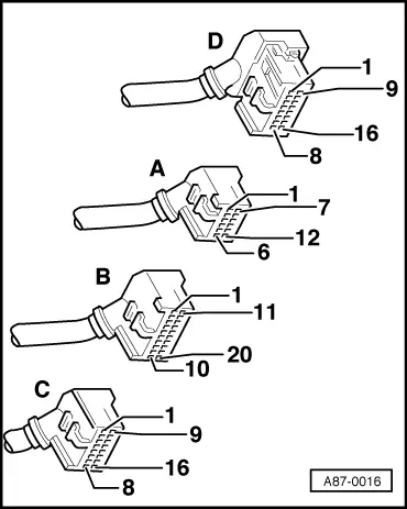
Connecting test box V.A.G 1598 A to connectors to operating and display unit for air conditioner/Climatronic -E87 (heating)

  • ‒ Switch off ignition.
  • ‒ Remove operating and display unit for air conditioner/Climatronic
    -E87 (heating) .
 
A87-0016
  • ‒ → Connect adapter cables V.A.G 1598/11 and V.A.G 1598/12 to unplugged connectors of operating and display unit for air conditioner/Climatronic -E87 (heating).

Notes:

  • ◆ Do not connect up operating and display unit for air conditioner/Climatronic -E87 (heating).
  • ◆ For measurement, connect test box V.A.G 1598 A to appropriate adapter cable.
  • ◆ For adapter cable V.A.G 1598/12, assignment of sockets is identical to connector pin assignment of operating and display unit for air conditioner/Climatronic -E87 (heating).
  • ◆ For adapter cable V.A.G 1598/11, assignment of sockets is not identical to connector pin assignment of operating and display unit for air conditioner/Climatronic -E87 (heating) =>Pin assignment, Page 01-234.

Pin assignment of test box V.A.G 1598 A with adapter cable V.A.G 1598/11

Notes:

  • ◆ For adapter cable V.A.G 1598/11, contact assignment of connectors A and B is not identical to assignment of sockets at test box V.A.G 1598 A.
  • ◆ For adapter cable V.A.G 1598/11, contact assignment of connector C is identical to assignment of sockets at test box V.A.G 1598 A.
  • ◆ For adapter cable V.A.G 1598/12, contact assignment of connector D is identical to assignment of sockets at test box V.A.G 1598 A.
  • ◆ As connectors to operating and display unit for air conditioner/Climatronic -E87 (heating) are split up over two adapter cables (V.A.G 1598/11 and 12) there is no earth connection for testing with adapter cable V.A.G 1598/11 connected. For performance of electrical check, it is therefore necessary when implementing certain test steps to take measurements with respect to a suitable earth point on the vehicle body or to use a second test box V.A.G 1598 A (when adapter cable V.A.G 1598/12 is connected, earth is applied to socket 13).

Connector A
Contact

V.A.G 1598 A socket

Connector B
Contact

V.A.G 1598 A socket

Connector B
Contact

V.A.G 1598 A socket

1

41

1

21

13

33

2

42

2

22

14

34

3

43

3

23

15

35

4

44

4

24

16

36

5

45

5

25

17

37

6

46

6

26

18

38

7

47

7

27

19

39

8

48

8

28

20

40

9

49

9

29

10

50

10

30

11

51

11

31

12

52

12

32

Checking

Test requirement:

 
A87-0312
  • ● All fuses OK

=> Current Flow Diagrams, Electrical Fault-finding and Fitting Locations binder

  • ● Test box adapter cables V.A.G 1598/11 and V.A.G 1598/12 connected to unplugged connectors of operating and display unit for air conditioner/Climatronic -E87 (heating)
  • ‒ → Set "Measurement" mode on vehicle diagnostic, testing and information system VAS 5051.

 
A87-0325
  • ‒ → Select type of measurement required in the various test steps on VAS 5051 by touching appropriate key on display of VAS 5051.

List of electrical checks at operating and display unit for air conditioner/Climatronic -E87 (heating)

Note:

Electrical checking is not provided for various items of information transmitted via the convenience data bus (Reading measured value block ).

Test step

Component checked

Page

1

- Power supply and earth connection of operating and display unit for air conditioner/Climatronic -E87 (heating)


01-238

2

- Temperature sensor -G89
- Senders -G151, -G152, -G261, -G262

01-240

3

- Wiring to control unit -J126 and fresh-air blower -V2

01-243

4

- Heating system control motors and corresponding potentiometers -V70/-G112,
- -V71/-G113, -V107/-G135, -V113/-G143, -V158/-G220, -V159/-G221


01-247

5

- Input for cut-in signal for actuating -E87 (heating) (e.g. from retrofitted auxiliary heater)

01-254

Test steps 1 to 6 > < Electrical check on heater