
A4 Mk2
|
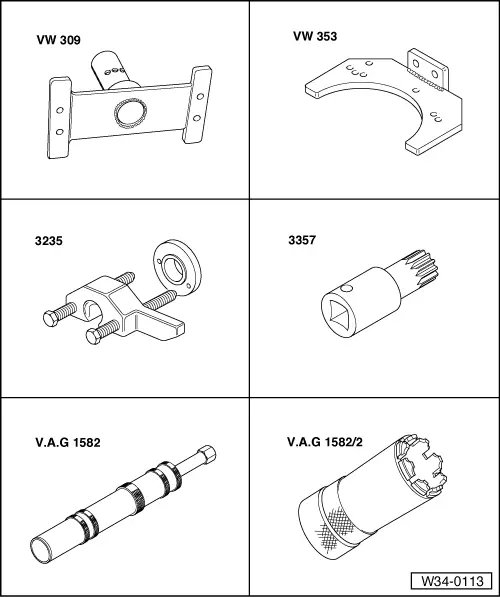
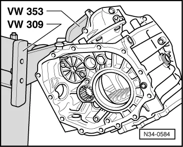
| Special tools and workshop equipment required |
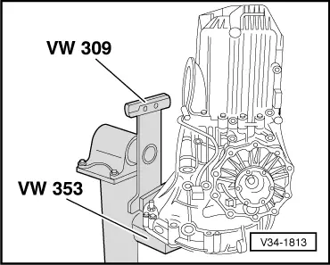
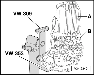
| t | Retaining plate -VW 309- |
| t | Gearbox support -VW 353- |
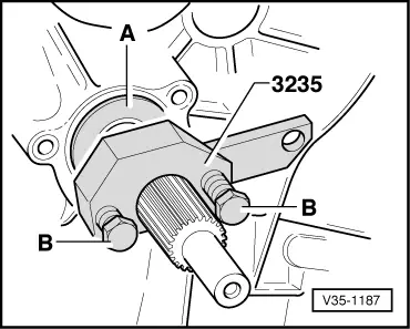
| t | Fitting tool -3235- or fitting tool -T10246- |
| t | Multi-point bit -3357- |
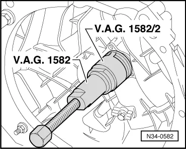
| t | Tapered roller bearing puller -V.A.G 1582- |
| t | Adapter -V.A.G 1582/2- |
|
|
 Note
Note
|
|
|
|
Note
|
|
|
|
|
|
|
|
|
|
|
|
|
|
Note
|
|
|
|
Note
|
|
Note
|
|
|
|
|
|
|
|
|
|
|
|
|
|
|
|
Note
|
|
Note
|
|
|
|