audi Workshop Repair Guides

Audi Workshop Service and Repair Manuals

Removing gearbox - vehicles with 2.5 ltr. TDI engine > < Removing gearbox - vehicles with 4-cylinder TDI engine
Installing gearbox - vehicles with 4-cylinder TDI engine
Installation is carried out in reverse sequence; note the following:
–  Use thread tap to remove any remaining locking fluid from all threaded holes which will accommodate self-locking bolts.
–  Always renew self-locking bolts and nuts.
–  Clean input shaft splines and (in the case of used clutch plates) the hub splines. Remove corrosion and apply only a very thin coating of grease for clutch plate splines -G 000 100- to the splines. Do not grease guide sleeve.
It should be possible to push the clutch plate back and forth slightly on the input shaft.
   
–  Check clutch release bearing for wear and renew if necessary.
–  If plastic ring -arrows- has come loose, service release bearing as required → Chapter.
–  Check clutch release bearing for wear and renew if necessary → Chapter.
  N30-0285
–  Check that dowel sleeves for centralising engine/gearbox -arrows- are in cylinder block, install if necessary.
–  Place intermediate plate on dowel sleeves at engine flange.
–  Before installing gearbox, tie electrical wires and brackets off to one side so that they are not trapped between the engine and the gearbox.
  A13-0682
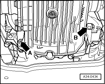
–  Lightly lubricate surface where plunger and clutch release lever make contact -arrow B- using copper grease -Z 381 351 TE-.
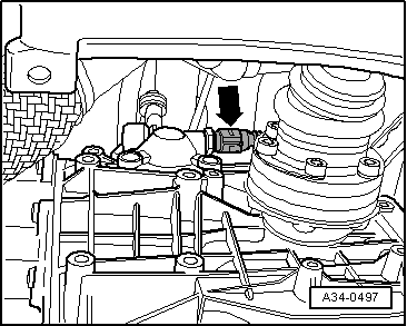
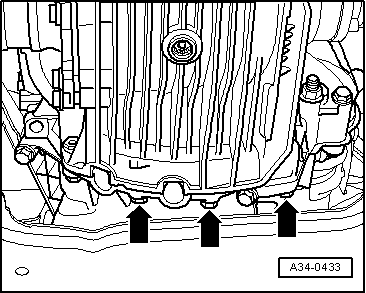
–  Raise gearbox far enough to be able to install clutch slave cylinder with bracket for hose/pipe assembly.
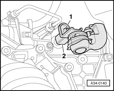
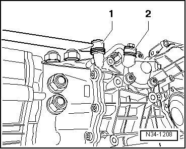
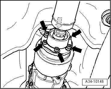
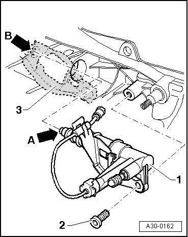
–  Guide slave cylinder -1- into opening in gearbox housing, keeping it as straight as possible (without tilting plunger -arrow A-), and insert in recess -arrow B- on clutch release lever -3-.
  Note
If the slave cylinder -1- is inserted at an angle, there is a danger that the plunger -arrow A- will be guided past the clutch release lever -3-.
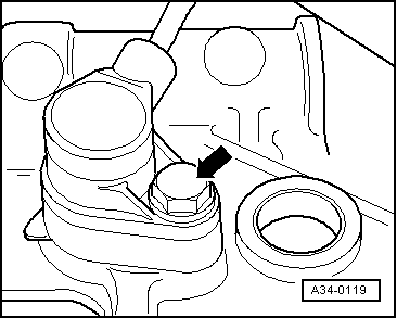
–  Secure slave cylinder with new bolt -2-. Tightening torque → Item
  Caution
t  After installing the slave cylinder press the clutch pedal carefully.
t  If you feel an unusually strong point of resistance when depressing the clutch pedal, you must not press it down further.
t  The plunger of the slave cylinder is likely to have been guided past the clutch release lever.
t  The slave cylinder would then be destroyed once pedal force exceeds approx. 300 N.
t  For comparison: normal pedal force is approx. 115 N.
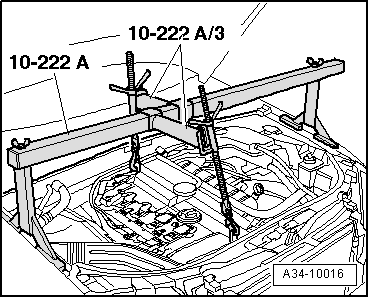
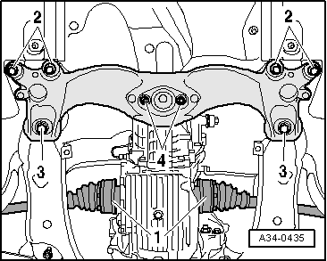
–  Insert gearbox, making sure there is sufficient clearance to drive shafts.
–  When aligning the gearbox with the engine, turn crankshaft back and forth slightly to make it easier to insert the gearbox input shaft splines into the clutch plate.
  A30-0162
–  Install engine/gearbox securing bolts -arrow A- and -arrow B-.
–  Install starter → Electrical system; Rep. Gr.27.
–  If fitted, secure all electrical wires to gearbox again.
  A34-0434
–  Press gearbox selector lever -2- onto gearbox selector shaft.
–  Renew nut -1- and tighten to torque setting. Tightening torque → Item
  A34-0140
–  Install push rod -1-; to do so, tighten hexagon socket head bolt. Tightening torque → Item
–  Secure connecting rod -2- for selector rod. Tightening torque → Item
  N34-1208
–  Attach connector -arrow- for reversing light switch -F4- on right side of gearbox.
  A34-0497
–  If fitted, install engine speed sender -G28- on left side of gearbox.
  A34-0119
–  Release front spindle -10 - 222 A /11-.
  A34-10016
–  Secure tunnel cross member on gearbox mounting -4-. Tightening torque → Item
–  Lift gearbox using engine and gearbox jack -V.A.G 1383 A-.
–  Secure tunnel cross member to body with bolts -3- and -2-. Tightening torques → Chapter
–  Carefully lower engine and gearbox jack -V.A.G 1383 A- and move it aside.
–  Secure drive shafts -1- → Rep. Gr.40.
  A34-0435
–  Tighten the bottom engine/gearbox securing bolts -arrows-.
  A34-0433
–  It is important to clean the threaded holes for the propshaft bolts to remove any remaining locking fluid. The threads can be cleaned with a thread tap.
–  Bolt propshaft onto gearbox -arrows- → Rear final drive 01R; Rep. Gr.39.
  A34-10146
–  Allow stop for torque reaction support to settle on rubber buffer for torque reaction support and tighten nuts -arrows-.
–  Install exhaust system so it is free of stress → Engine, mechanics; Rep. Gr.26 for the relevant engine code.
  A10-10288
–  Remove support bracket -10 - 222 A-.
  A34-10016
–  Tighten upper engine/gearbox securing bolts -arrows 1- and -arrows 2-. Please note that there may be brackets for wires/lines secured with the bolts -arrows 2-.
  A34-0704
–  Secure coolant expansion tank -arrow-.
–  Plug in connector for coolant shortage indicator switch -F66- at bottom of expansion tank.
  A10-0989
–  Secure fuel filter -arrows-.
–  Secure electrical wiring to fuel filter bracket.
–  Install engine cover panel.
–  Check selector mechanism setting and adjust if necessary → Chapter.
–  Check gear oil level in gearbox → Chapter.
  A10-10285
–  Install noise insulation (front and rear) with fasteners -1 … 3-.
–  Follow the steps required after connecting the battery. → Electrical system; Rep. Gr.27.
Tightening torques
  Note
t  Tightening torques apply only to lightly greased, oiled, phosphated or black-finished nuts and bolts.
t  Additional lubricant such as engine or gearbox oil may be used, but do not use graphite lubricant.
t  Do not use parts which have been degreased.
t  Tolerance for tightening torques ±15%.
  A10-1320
Engine/gearbox attachment (2.0 ltr. TDI engine)
  A37-10065
ItemBoltNm
1M12x10565
2 1)M12x8065
3 1)M12x9065
4 2)M12x8065
5, 7M12x9565
6 2)M12x10565
8M10x5045
9, 10, 11M10x4545
ADowel sleeves for centralising
1) Secures starter to gearbox
2) With bracket for wiring

   
Component Nm
Heat shields above drive shafts to gearbox23
Stop for torque reaction support28
Bracket for noise insulation to subframe10


Removing gearbox - vehicles with 2.5 ltr. TDI engine > < Removing gearbox - vehicles with 4-cylinder TDI engine