
A4 Mk2
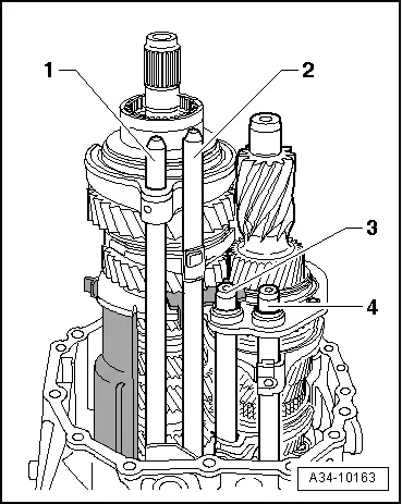
| Removing and installing input shaft, hollow shaft, pinion shaft and selector rods - exploded view |

| 1 - | Bolt, 24 Nm |
| q | Apply locking fluid -AMV 185 101 A1- when fitting |
| 2 - | Leaf spring |
| 3 - | Intermediate piece |
| q | Insert in hole in gearbox housing. |
| 4 - | Clutch release lever |
| q | With release bearing |
| 5 - | Bolt, 24 Nm |
| q | 2 x |
| q | Apply locking fluid -AMV 185 101 A1- when fitting |
| 6 - | Retaining piece |
| q | For guide sleeve |
| 7 - | Guide sleeve |
| q | With oil seal |
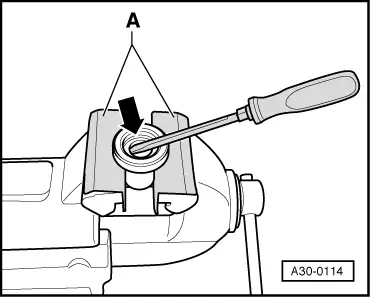
| q | Removing input shaft oil seal → Fig. |
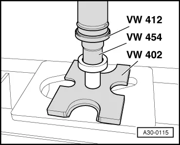
| q | Installing input shaft oil seal → Fig. |
| 8 - | O-ring |
| q | Always renew |
| q | Lubricate with gear oil |
| q | Insert in circumferential groove in gearbox cover |
| 9 - | Circlip |
| q | Insert in circumferential groove in input shaft |
| 10 - | Selector rod for 5th and 6th gear |
| q | Installation position → Fig. |
| q | Only to be renewed complete with pinned selector fork for 5th and 6th gear |
| 11 - | Selector rod for 3rd and 4th gear |
| q | Installation position → Fig. |
| q | Only to be renewed complete with pinned selector fork for 3rd and 4th gear |
| q | Modification: with spring-loaded selector fork → Fig., allocate via → Electronic parts catalogue “ETKA”. |
| 12 - | Input shaft |
| q | Dismantling and assembling → Chapter |
| 13 - | Bearing mounting |
| q | Clean locking fluid out of tapped holes (using thread tap or similar) |
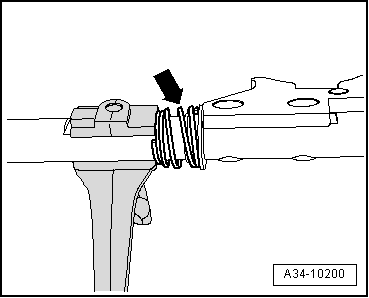
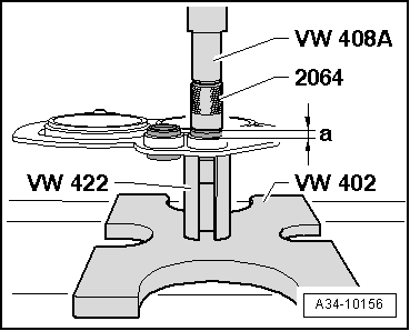
| q | Pressing out and pressing in ball sleeves for selector rods → Fig. |
 Note
Note| t | The roller bearing outer races on the input shaft and hollow shaft cannot be renewed individually. |
| t | The roller bearing outer races must not have any radial clearance in the bearing mounting. |
| 14 - | Bolt, 30 Nm |
| q | 6 x |
| q | Clean thread and apply locking fluid -AMV 185 101 A1- when fitting |
| 15 - | Retaining plate |
| q | Installation position: machined side faces towards gearbox housing (can only be installed in one position). |
| 16 - | Shim “S4” |
| q | Table of adjustments → Chapter |
| 17 - | Pinion shaft |
| q | With double angular contact ball bearing and tapered roller bearing inner race |
| q | Dismantling and assembling → Chapter |
| 18 - | Needle bearing |
| q | For pinion shaft/hollow shaft |
| 19 - | Shim “S3” |
| q | Table of adjustments → Chapter |
| 20 - | Hollow shaft |
| q | With pressed-on gears for 5th and 6th gear |
| q | Dismantling and assembling → Chapter |
| 21 - | Oil guide panel |
| 22 - | Gearbox housing |
| q | With differential and flange shafts |
Note
|
|
|
|
Note
|
|
|
|