audi Workshop Repair Guides

Audi Workshop Service and Repair Manuals

Servicing toothed belt drive - vehicles to 04.2003 > < Removing and installing vibration damper
Removing and installing bracket for ancillaries
Special tools and workshop equipment required
   
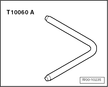
t  Locking pin -T10060 A- or locking pin -T10060-
Removing
  Caution
Observe notes on procedure for disconnecting the battery → Electrical system; Rep. Gr.27.
–  Disconnect earth wire at battery with ignition switched off.
–  Drain off coolant → Chapter.
–  Remove intake manifold → Rep. Gr.24.
–  Remove coolant pipe (small) → Chapter.
–  Remove thermostat housing → Chapter.
  W00-10235
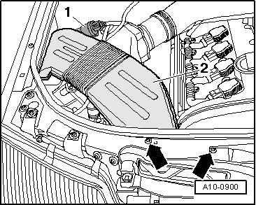
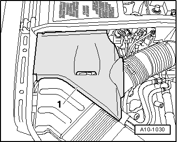
–  If fitted, detach cover -1- on right of engine compartment.
  A10-1030
–  Disengage solenoid valve 1 for activated charcoal filter system -N80- at air duct.
–  Remove bolts -arrows-.
–  Remove air duct -2-.
  Note
  A10-0900
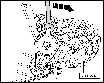
Before removing, mark direction of rotation of poly V-belt with chalk or felt-tipped pen. If the belt runs in the opposite direction when it is refitted, this can cause breakage.
–  Turn the tensioner in the direction of the -arrow- to slacken the poly V-belt.
  A13-0083
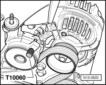
–  Lock tensioner for poly V-belt in position with locking pin -T10060 A- or -T10060-.
–  Remove poly V-belt.
  N13-0620
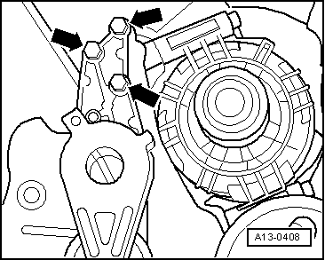
–  Remove bolts -arrows-.
–  Remove tensioner for poly V-belt together with engine lifting eye.
–  Remove alternator → Electrical system; Rep. Gr.27
  A13-0408
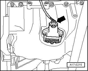
–  Unplug electrical connector -arrow- at oil level/oil temperature sender -G266-.
  A17-0215
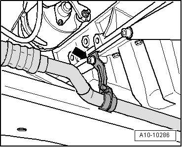
–  Unbolt refrigerant pipe bracket from sump -arrow-.
  A10-10286
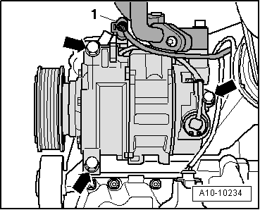
–  Unplug electrical connector -1- for magnetic clutch on air conditioner compressor.
  WARNING
The air conditioner refrigerant circuit must not be opened.
–  Unscrew air conditioner compressor from bracket -arrows-.
  Note
To prevent damage to the refrigerant lines, ensure that the pipes and hoses are not stretched, kinked or bent.
–  Tie up air conditioner compressor to vehicle, with lines attached.
  A10-10234
–  Unscrew front bolts -arrows- for power steering pump.
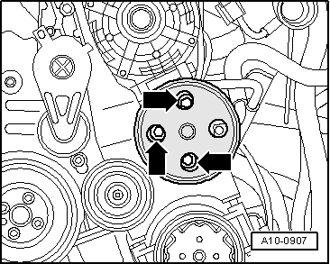
  A10-0907
–  Unscrew rear bolt -arrow- for power steering pump.
–  Move power steering pump aside and place onto longitudinal member. Leave pipes connected.
  A10-0966
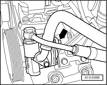
–  Unscrew bolt for connector retaining plate from intake manifold bracket.
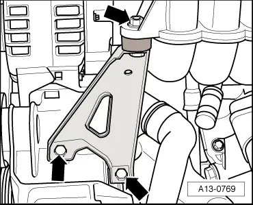
–  Unscrew bolts -bottom arrows- and remove intake manifold bracket.
  A13-0769
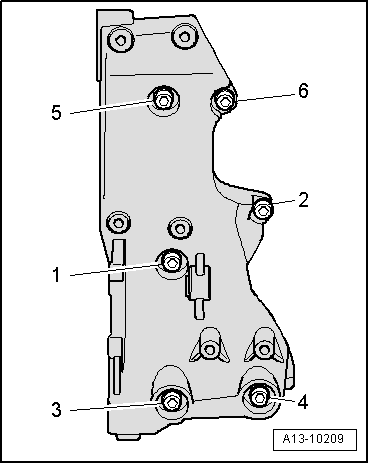
–  Remove bolts -1 ... 6- on bracket for ancillaries.
Installing
Installation is carried out in the reverse order; note the following:
  Note
t  Always remove remaining locking fluid from the tapped holes in the cylinder block prior to assembly. Otherwise the new bolts can seize when screwed in, and then shear off if they have to be subsequently removed.
t  This can be done using a thread tap.
–  Insert bolts securing bracket for ancillaries with locking fluid; Locking fluid → Parts catalogue.
–  Tighten bolts in the sequence -1 ... 6-.
–  Install power steering pump → Running gear, front-wheel drive and four-wheel drive; Rep. Gr.48.
–  Install air conditioner compressor → Air conditioning system; Rep. Gr.87.
–  Install alternator → Electrical system; Rep. Gr.27
–  Install poly V-belt → Chapter.
–  Install thermostat housing → Chapter.
–  Install coolant pipe (small) → Chapter.
–  Install intake manifold → Rep. Gr.24.
–  Observe notes on procedures required after connecting battery → Electrical system; Rep. Gr.27.
–  Fill cooling system → Anchor.
Tightening torques
  A13-10209
ComponentNm
Idler roller to bracket for ancillaries25
Bracket for ancillaries to cylinder block40 1)
Bracket for intake manifold to bracket for ancillaries23
Tensioner for poly V-belt to bracket for ancillaries23
l  1) Install using locking fluid; for locking fluid refer to → Parts catalogue.


Servicing toothed belt drive - vehicles to 04.2003 > < Removing and installing vibration damper