
A4 Mk2
|
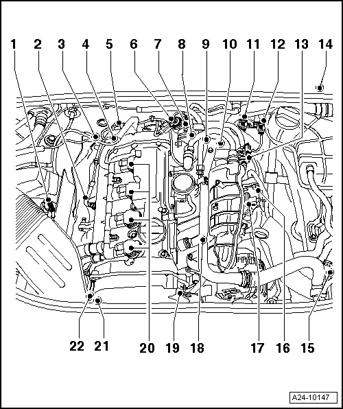
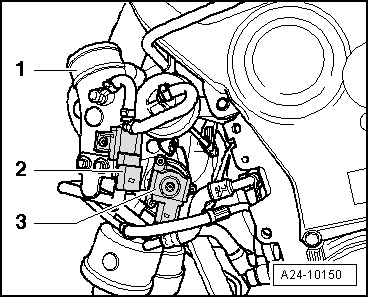
| 1 - | Air mass meter -G70- |
| q | → Fig. |
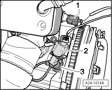
| 2 - | Lambda probe -G39- and Lambda probe heater -Z19- |
| 3 - | Lambda probe after catalytic converter -G130- and Lambda probe heater 1 after catalytic converter -Z29- |
| q | → Fig. |
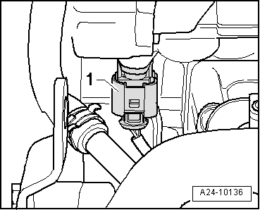
| 4 - | Coolant temperature sender -G62- |
| q | → Fig. |
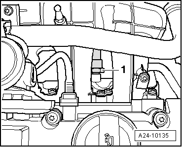
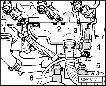
| 5 - | Camshaft control valve 1 -N205- |
| q | → Fig. |
| 6 - | Fuel pressure regulating valve -N276- |
| q | → Fig. |
| 7 - | Single-plunger high-pressure pump |
| 8 - | Fuel pressure sender, low pressure -G410- |
| q | 15 Nm |
| 9 - | Intake manifold flap motor -V157- with intake manifold flap potentiometer -G336- |
| 10 - | Engine speed sender -G28- |
| q | → Fig. |
| 11 - | Activated charcoal filter solenoid valve 1 -N80- |
| 12 - | 6-pin connector |
| q | For Lambda probe -G39- and Lambda probe heater -Z19- (black) → Fig. |
| 13 - | 6-pin connector |
| q | Lambda probe after catalytic converter -G130- and Lambda probe 1 heater after catalytic converter -Z29- (brown connector) |
| 14 - | Engine control unit -J623- |
| q | Removing and installing → Rep. Gr.24 |
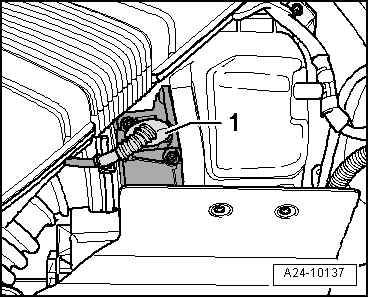
| 15 - | Charge pressure sender -G31- |
| q | → Fig. |
| 16 - | Throttle valve module -J338-, throttle valve drive (electric throttle operation) -G186- |
| q | Throttle valve drive angle sender 1 -G187- and throttle valve drive angle sender 2 -G188- |
| q | After the throttle valve module -J338- has been renewed, it must be adapted to the engine control unit -J623- (Basic setting, Display group 60), see “Guided Fault Finding”. |
| q | → Fig. |
| 17 - | Intake air temperature sender -G42- |
| q | → Fig. |
| 18 - | Fuel pressure sender -G247- |
| q | → Fig. |
| 19 - | Hall sender -G40- (camshaft position sensor) |
| q | → Fig. |
| 20 - | Ignition coils with output stages |
| q | Ignition coil 1 with output stage -N70- |
| q | Ignition coil 2 with output stage -N127- |
| q | Ignition coil 3 with output stage -N291- |
| q | Ignition coil 4 with output stage -N292- |
| q | Puller -T40039- is required for removing ignition coils from cylinder head. |
| q | Removing and installing → Rep. Gr.24 |
| 21 - | Turbocharger air recirculation valve -N249- |
| q | Located directly on turbocharger → Fig. |
| 22 - | Charge pressure control solenoid valve -N75- |
| q | Located directly on turbocharger → Fig. |
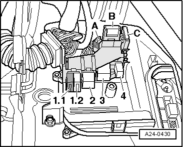
| A - | Diagnostic connector |
| q | In driver's knee restraint |
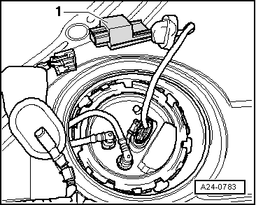
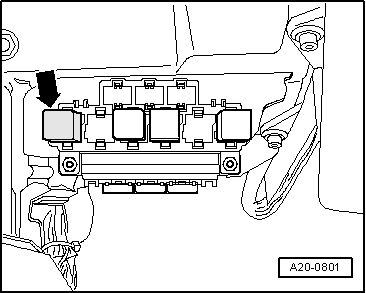
| B - | Fuel pump control unit -J538- |
| q | → Fig. |
| C - | “EPC” warning lamp |
| q | In instrument cluster |
| D - | “MIL” exhaust emissions warning lamp |
| q | In instrument cluster |
| E - | 8-pin connector for injectors |
| q | → Fig. |
| F - | Connector |
| q | For Hall sender -G40- and fuel pressure sender -G247- |
| q | → Fig. |
| G - | Brake light switch - F- and brake pedal switch -F63- |
| q | → Fig. |
| H - | Accelerator position sender -G79- and accelerator position sender 2 -G185- |
| q | On accelerator pedal (both senders are accommodated in one housing) |
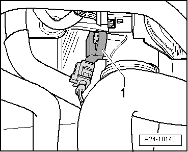
| I - | Clutch pedal switch -F36- |
| q | → Fig. |
| J - | Relay and fuse holder in electronics box |
| q | → Fig. |
| K - | Radiator fan control unit -J293- |
| q | Installed in left-side radiator fan (in direction of travel) |
| L - | Injectors |
| q | In fuel rail |
| q | Injector, cylinder 1 -N30- |
| q | Injector, cylinder 2 -N31- |
| q | Injector, cylinder 3 -N32- |
| q | Injector, cylinder 4 -N33- |
| q | Removing and installing → Rep. Gr.24 |
| The fuel injectors are high-pressure injectors. They inject fuel at high pressure (maximum approx. 120 bar) directly into the cylinder. |
| M - | Knock sensor 1 -G61- |
| q | For cylinders 1 and 2 |
| q | Tightening torque: 20 Nm |
| q | → Fig. |
| N - | Knock sensor 2 -G66- |
| q | For cylinders 3 and 4 |
| q | Tightening torque: 20 Nm |
| q | → Fig. |
| O - | Oil pressure sender -G10- |
| q | → Fig. |
|
|
|
|
|
|
|
|
|
|
|
|
|
|
|
|
|
|
 Note
Note
|
|
|
|
|
|
|
|
|
|
|
|
|
|