
A4 Mk2
| Hose connection diagram for exhaust gas recirculation |
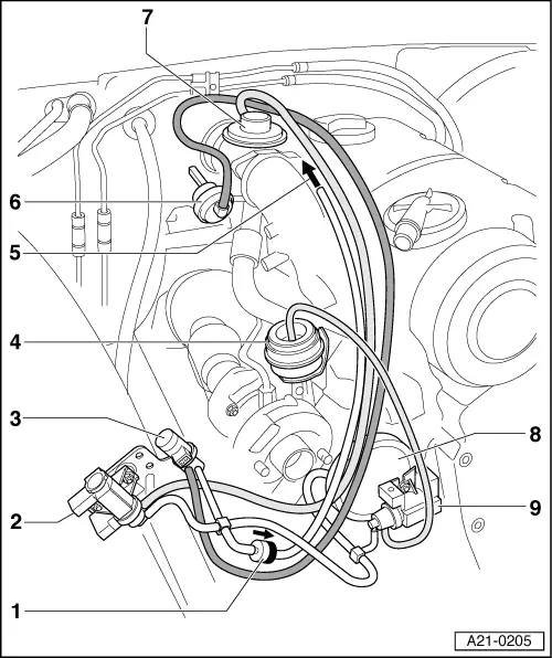
| 1 - | Non-return valve |
| q | Note installation position (light side/dark side) - as shown in illustration |
| 2 - | Exhaust gas recirculation valve -N18- |
| q | Installation position: front right of engine compartment |
| 3 - | Variable intake manifold flap change-over valve -N239- |
| 4 - | Vacuum unit for charge pressure control |
| 5 - | To tandem pump |
| 6 - | Vacuum unit for intake manifold flap |
| 7 - | Mechanical exhaust gas recirculation valve |
| q | Can only be renewed together with intake connecting pipe |
| q | Checking → Chapter |
| 8 - | Vacuum reservoir |
| 9 - | Charge pressure control solenoid valve -N75- |