audi Workshop Repair Guides

Audi Workshop Service and Repair Manuals

Servicing work on pulley end > < Dismantling and assembling engine
Moving lock carrier to service position
Special tools and workshop equipment required
   
t  Front-end service sleeves -3369-
  W00-0198
Procedure
–  Remove both front wheels.
–  Vehicles with auxiliary heater: remove bolts -arrows- securing exhaust pipe for auxiliary/additional heater to noise insulation.
  A10-0407
–  Release quick-fasteners -1- and -2- and take off front noise insulation. Leave rear noise insulation in position.
  A10-1320
–  Detach air intake hose -1- going to charge air cooler at lock carrier (bottom left).
  WARNING
The air conditioner refrigerant circuit must not be opened.
–  Disengage refrigerant line at bracket -2-.
  A10-1038
–  Detach turbocharger air intake hose -1- at lock carrier (bottom right).
  A21-0200
–  Detach resonator from retainer -arrow-.
  Note
Air intake hose remains connected.
  A10-10281
–  Remove bumper cover (front) → Rep. Gr.63.
–  Remove air duct in front of charge air cooler -arrows-.
  A21-0199
–  Remove bolts -arrows-.
–  Remove air ducts -1- and -2-.
  A10-0746
–  Disengage the electrical connectors -1- and -2- from retainer and move wiring clear.
  A10-10282
–  Remove engine compartment seal from lock carrier and wing panel flanges.
–  Remove bolts -arrows- at lock carrier (left and right).
  A10-1047
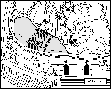
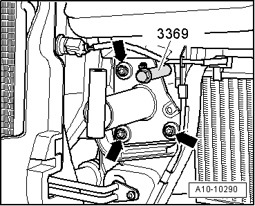
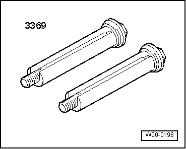
–  Screw in front-end service sleeves -3369- (left and right) in the holes.
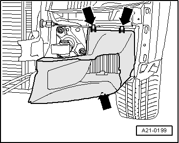
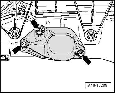
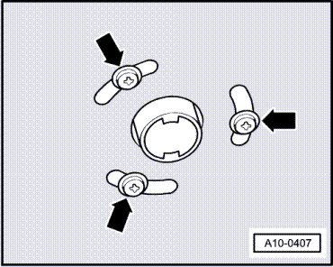
–  Unscrew bolts -arrows- from impact dampers (left and right).
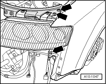
–  Carefully pull the lock carrier forward.
Installing
Installation is carried out in the reverse order; note the following:
  Note
t  
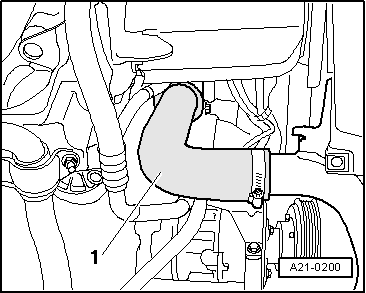
Hose connections and hoses for charge air system must be free of oil and grease before assembly. Do NOT use lubricant.
t  Secure all hose connections with the correct type of hose clips (same as original equipment) → Electronic parts catalogue.
t  To ensure that the charge air hoses can be properly secured at their connections, spray rust remover onto the worm thread of used hose clips before installing.
–  Install lock carrier with attachments → Rep. Gr.50.
  A10-10290
–  Allow stop for torque reaction support to rest on rubber buffer for torque reaction support under its own weight and tighten nuts -arrows-.
–  Install bumper cover (front) → Rep. Gr.63.
Tightening torques
  A10-10288
ComponentNm
Stop for torque reaction support to lock carrier28
Hose clips (9 mm wide)3
Hose clips (13 mm wide)5.5


Servicing work on pulley end > < Dismantling and assembling engine