
A4 Mk2
|
 Note
Note |
|
 Caution
|
|
|
|
Note
|
|
|
|
|
|
|
|
|
|
|
|
|
|
|
|
Note
|
|
|
|
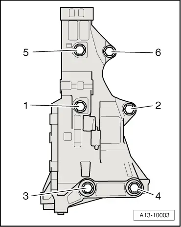
| Component | Nm | ||||
| Bracket for ancillaries to cylinder block | 45 | ||||
| Idler roller for toothed belt to bracket for ancillary units | 40 + 90° 1)2) | ||||
| Stop for torque reaction support to lock carrier | 28 | ||||
| Hose clips (9 mm wide) | 3 | ||||
| Hose clips (13 mm wide) | 5.5 | ||||
| |||||