
A4 Mk2
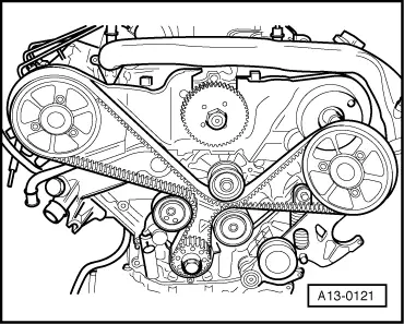
| Removing and installing toothed belt |
| Special tools and workshop equipment required |
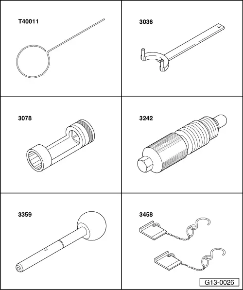
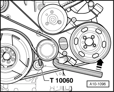
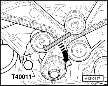
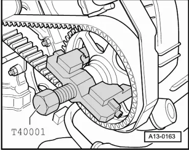
| t | Locking pin -T40011- |
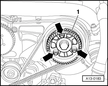
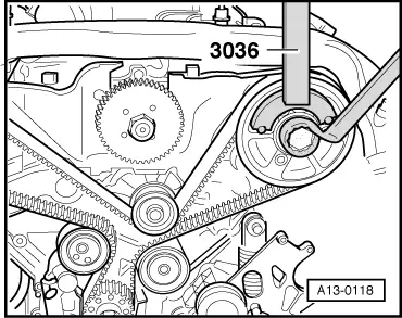
| t | Counterhold tool -3036- |
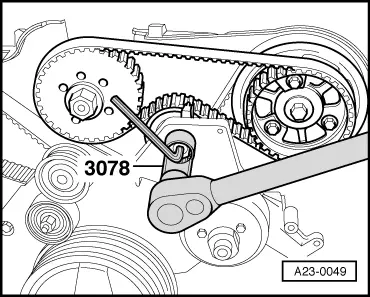
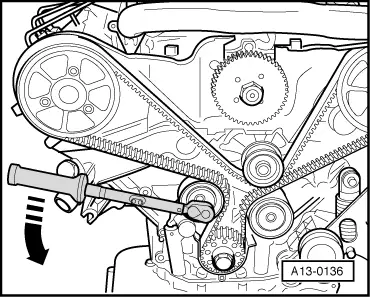
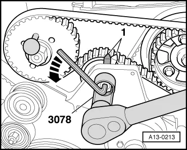
| t | Socket (22 mm) -3078- |
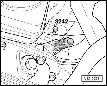
| t | Locking pin -3242- |
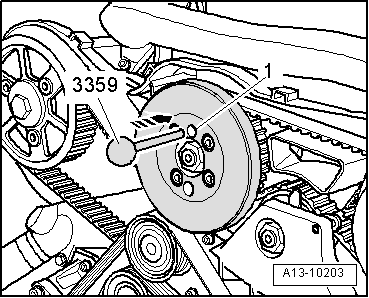
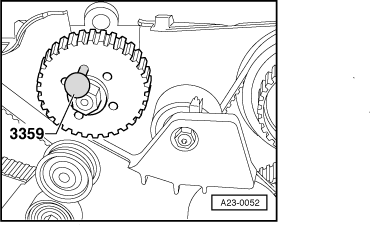
| t | Diesel injection pump locking pin -3359- |
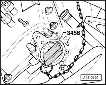
| t | Camshaft clamp -3458- |
|
|
|
|
|
|
|
|
|
|
|
|
|
|
|
|
 Note
Note
|
|
|
|
Note
Note |
|
|
|
Note
|
|
 Caution
Note
|
|
 WARNING
|
|
|
|
Note
|
|
|
|
Note
|
|
|
|
Note |
|
|
|
Note
|
|
|
|
|
|
Note
|
|
Note
|
|
|
|
|
|
|
|
|
|
|
|
|
|
|
|
Note
|
|
|
|
|
|
|
|
|
|
|
|
Note
|
|
| Component | Nm |
| Camshaft sprocket to camshaft | 75 |
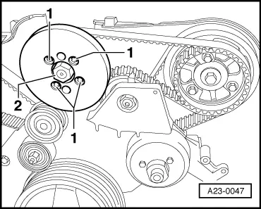
| Vibration damper to injection pump sprocket | 22 |
| Drive sprocket for injection pump to camshaft | 22 |
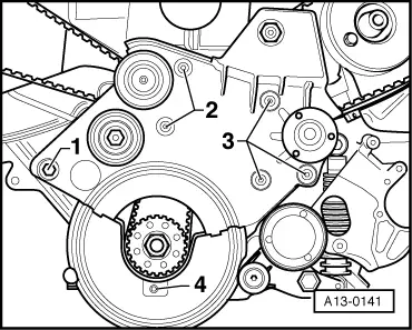
| Tensioning roller for injection-pump toothed belt to bracket for viscous fan | 36 |
| Exhauster pump to cylinder head | 10 |
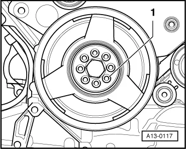
| Vibration damper to crankshaft sprocket | 22 |
| Screw plug in cylinder block | 35 |
| Torque reaction support to top section of sump | 40 |
| Hose clips (9 mm wide) | 3 |
| Hose clips (13 mm wide) | 5.5 |