
A4 Mk2
| Dismantling and assembling pistons and conrods |

| 1 - | 30 Nm +90° (1/4 turn) further |
| q | Renew |
| q | Lubricate threads and contact surface |
| q | To measure radial clearance, tighten to 30 Nm but do not turn further |
| 2 - | Conrod bearing cap |
| q | Do not interchange |
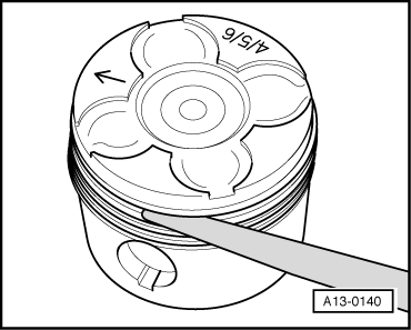
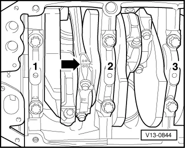
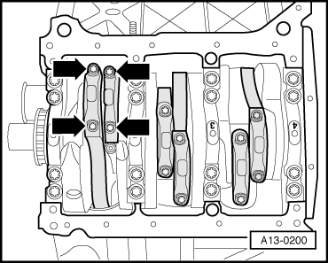
| q | Mark cylinder allocation with a coloured pen -B- → Fig. |
| q | Installation position: Note position of lugs -A- on casting → Fig. |
| 3 - | Bearing shell |
| q | Note installation position |
| q | Do not interchange used bearing shells (mark positions) |
| q | Bearing shells worn down to nickel layer must be renewed |
| q | Axial clearance of one pair of conrods New: 0.20 ... 0.44 mm; Wear limit: 0.60 mm |
| q | Measuring radial clearance → Chapter |
| 4 - | Conrod |
| q | Only renew as a complete set |
| q | Mark cylinder allocation with a coloured pen -B- → Fig. |
| q | Installation position: Note position of lugs -A- on casting → Fig. |
| q | Measuring radial clearance → Chapter |
| 5 - | Circlip |
| 6 - | Piston pin |
| q | If difficult to move, heat piston to approx. 60 °C |
| q | Remove and install using drift -VW 222 A- |
| 7 - | Piston |
| q | With combustion chamber |
| q | Mark installation position and cylinder number |
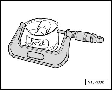
| q | Checking → Fig. |
| q | Installation position and allocation of piston/cylinder → Fig. |
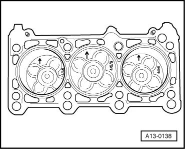
| q | Arrow on piston crown faces centre of engine |
| q | Install using piston ring clamp |
| q | If cracking is visible on piston skirt, renew piston |
| q | Checking piston projection at “TDC” → Chapter |
| q | Piston and cylinder dimensions → Chapter |
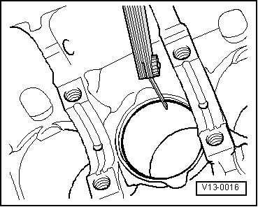
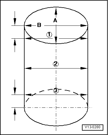
| q | Checking cylinder bore → Fig. |
| 8 - | Piston rings |
| q | Offset gaps by 120° |
| q | Use piston ring pliers to remove and install |
| q | “TOP” must face towards piston crown |
| q | Checking ring gap → Fig. |
| q | Checking ring-to-groove clearance → Fig. |
| 9 - | 9 Nm |
| 10 - | Oil spray jet |
| q | For piston cooling |
|
|
| Piston ring Dimensions in mm | New | Wear limit |
| 1st compression ring | 0.20 … 0.40 | 0.8 |
| 2nd compression ring | 0.80 … 1.00 | 1.4 |
| Oil scraper ring | 0.25 … 0.50 | 0.8 |
|
|
| Piston ring Dimensions in mm | New | Wear limit |
| 1st compression ring | 0.100 … 0.135 | 0.150 |
| 2nd compression ring | 0.045 … 0.085 | 0.110 |
| Oil scraper ring | 0.025 … 0.065 | 0.090 |
|
|
 Note
Note
|
|
 Caution
Note
|
|
Note
|
|