
A4 Mk2
| Removing engine |

| Special tools and workshop equipment required |
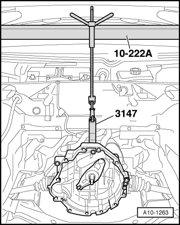
| t | Support bracket -10-222 A- |
| t | Removal lever -80-200- |
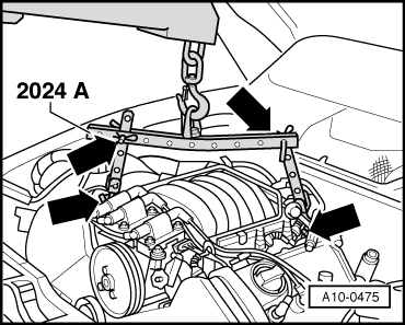
| t | Lifting tackle -2024 A- |
| t | Gearbox support -3147- |
| t | Drip tray -V.A.G 1306- |
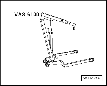
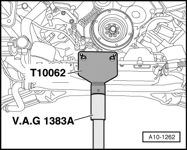
| t | Engine and gearbox jack -V.A.G 1383 A- |
|
|
|
|
 Note
Note
|
|
 Caution
|
|
|
|
 WARNING
|
|
|
|
|
|
|
|
Note
|
|
|
|
|
|
Note
|
|
|
|
|
|
|
|
|
|
|
|
|
|
|
|
|
|
Note
|
|
|
|
Note
|
|
|
|
Note
|
|
|
|
|
|
|
|
|
|
|
|
|
|
Note
|
|
|
|
|

|
|
|
|
|
|
|
Note |
|
|
|
|
|
|
|
|
|
|
|
Note
|
|
Note
Note
Note
|
|
|
|
|
|
|
|
Note
|
|
|
|
|
|
|
|
|
|
|
|
Note |
|
|
|
Note
|
|
Note
|
|
Note
|
|
Note
|
|
|
|
|
|
|
|
|
|
Note
|
|
|
|
|
|
|
|
Note
Note
Note
|
|