
A4 Mk2
| Removing and installing camshaft timing chain |
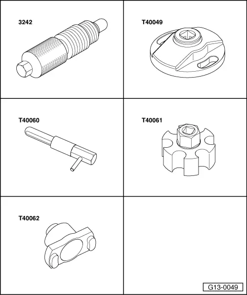
| Special tools and workshop equipment required |
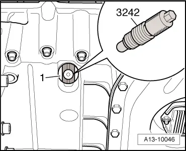
| t | Locking pin -3242- |
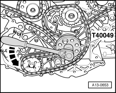
| t | Special wrench -T40049- |
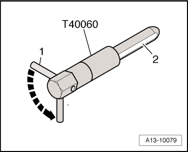
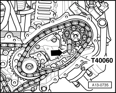
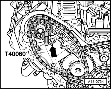
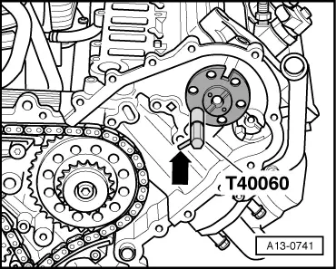
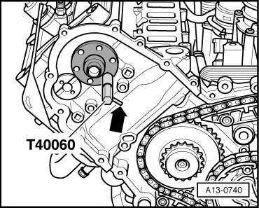
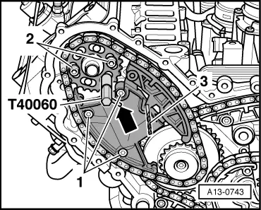
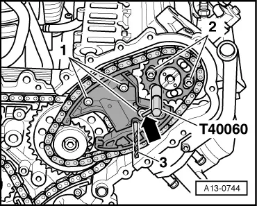
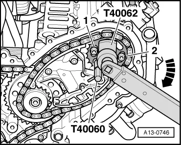
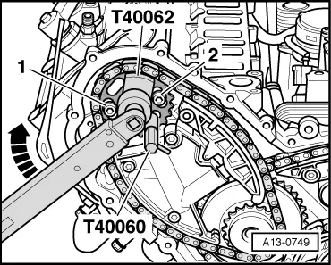
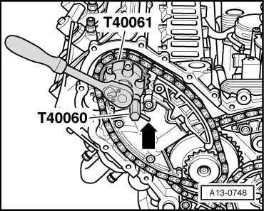
| t | 2x Adjustment pin -T40060- |
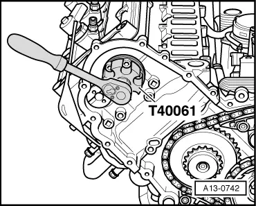
| t | Adapter -T40061- |
| t | Adapter -T40062- |
| t | Drill bit 3.3 mm Ø (2x) |
|
 Caution
 Note
Note |
|
|
|
|
|
|
|
|
|
|
|
 WARNING
|
|
|
|
|
|
|
|
Note
|
|
|
|
Note |
|
|
|
|
|
|
|
|
|
|
|
|
|
|
|
|
|
|
|
|
|
|
|
|
|
| Component | Nm | ||||
| Chain tensioner to cylinder head | 5 + 90° 1)2) | ||||
| Camshaft sprocket to camshaft | 23 | ||||
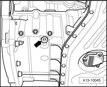
| Screw plug in top section of sump | 35 | ||||
| |||||