audi Workshop Repair Guides

Audi Workshop Service and Repair Manuals

Removing cylinder head - vehicles up to 09.2005 > < Cylinder head cover - exploded view
Removing and installing cylinder head cover
   
Removing and installing cylinder head cover
Special tools and workshop equipment required
t  Socket, 14 mm -3150- for vehicles up to 09.2005
t  Torque wrench -V.A.G 1331-
t  Ratchet -V.A.G 1331/1-
t  Puller -T10055- with -T10055/1-
t  Socket -T40055-

   
t  Tool insert, AF 19 -V.A.G 1331/5- for vehicles from 09.2005 onwards
  W00-1127
Removing
  Note
The following description shows the removal and installation of the left cylinder head cover. The procedure for the other side is the same, except that some steps are not required.
–  Carefully pull engine cover panel off four retaining pins one after the other -arrows-.
  A10-10171
–  Unbolt coolant expansion tank -arrow-.
–  Detach electrical connector at coolant shortage indicator switch -F66- on coolant expansion tank (bottom).
–  Lay aside coolant expansion tank with coolant hoses -1- and -2- connected.
  A10-10326
–  Unplug electrical connector -4-.
–  Disconnect air intake hose -5-.
–  Remove bolts -1 … 3- and detach throttle valve module -J338- together with intake connecting pipe.
  A15-10120
–  Remove bolts -1 … 4- and detach bracket for intake connecting pipe from cylinder head.
  A15-10121
–  Remove oil filler neck. To do so, lift tab -1- and turn oil filler neck anti-clockwise -arrow-.
  A15-10028
  Caution
Observe rules for cleanliness when working on the injection system → Chapter.
–  Pull release pins upwards -arrow- and pull return line connections off injectors.
–  Mark high-pressure pipes to ensure they are re-connected to the same injectors.
  A15-10029
Vehicles up to 09.2005:
–  Remove electrical connector -arrow- for Lambda probe -G39- from retainer.
–  Unplug electrical connector and move wiring clear.
–  Detach bracket for electrical connector for Lambda probe -G39- from cylinder head cover.
  A10-10180
–  Unplug electrical connectors -5- at fuel rail and injectors.
–  Move clear electrical wiring harness at fuel rail.
–  Loosen union nuts for injector pipes -1, 6, 7- using socket -T40055-.
–  Loosen union nut for high-pressure pipe -3- at fuel rail.
–  Remove bolts -2- and -4- and detach fuel rail.
  A15-10030
Vehicles from 09.2005 onwards:
–  Unbolt bracket -5- for wiring harness at cylinder head cover.
–  Unplug electrical connectors -1 ... 4- at fuel rail and injectors.
–  Move electrical wiring harness clear.
  A15-10286
–  Loosen union nuts for high-pressure pipes -1 ... 6- using tool insert, AF 19 -V.A.G 1331/5- and socket -T40055-.
–  Detach high-pressure pipes.
  A15-10287
All vehicles (continued):
–  Unbolt covers for injectors -arrows-.
–  Pull covers upwards and turn them 1/4 turn (90°).
  A15-10031
–  Unbolt injectors -arrows-.
  A15-10032
–  Pull out injectors using puller -T10055- with adapter -T10055/1-.
  Caution
t  Mark cylinder numbers on injector units.
t  Used injectors must always be re-installed on the same cylinder.
  A15-10033
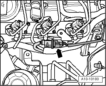
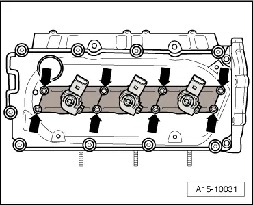
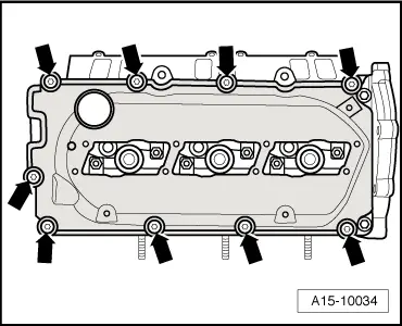
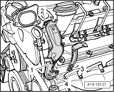
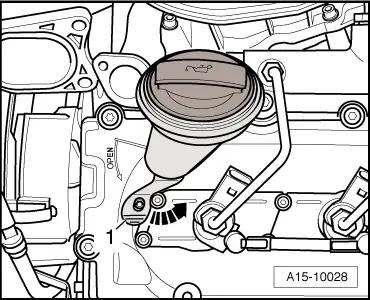
–  Loosen cylinder head cover bolts -arrows- in diagonal sequence.
–  Remove bolts and take off cylinder head cover.
Installing
Installation is carried out in the reverse order; note the following:
  Note
t  Renew gaskets and bolts for cylinder head cover if damaged.
t  Renew gaskets, seals and O-rings.
t  Hose connections and hoses for charge air system must be free of oil and grease before assembly.
t  Secure all hose connections with the correct type of hose clips (same as original equipment) → Electronic parts catalogue.
t  To ensure that the charge air hoses can be properly secured at their connections, spray rust remover onto the worm thread of used hose clips before installing.
–  Tighten cylinder head cover bolts diagonally and in stages.
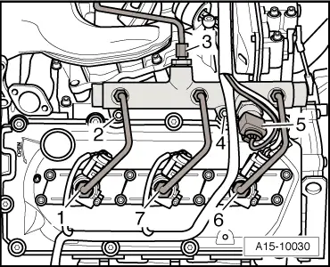
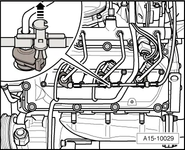
Instructions for installing injectors:
l  Before installation, make sure the injectors and their surroundings are clean. If necessary use a clean cloth to wipe out the injector slot, taking care not to cause damage (do not use sharp-edged tools).
l  Always install new seals and gaskets. Lubricate all seals and gaskets lightly with engine oil or assembly oil before installing.
l  
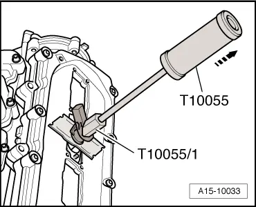
The injectors must be completely undamaged. To remove the old copper seal from the injector, clamp the seal carefully in a vice so that it is just held between the jaws without turning. Then carefully pull and twist the injector out of the copper seal by hand.
l  
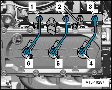
When an injector is renewed, also renew the injector pipe and clamping piece at the same time.
l  Used injectors and injector pipes may only be re-installed on the same cylinder.
  A15-10034
–  Install injectors.
–  Tighten union nuts on high-pressure pipes hand-tight to start with.
–  Ensure that high-pressure pipes are not under tension.
–  To tighten unions of high-pressure pipes, use torque wrench -V.A.G 1331- with ratchet -V.A.G 1331/1- and socket -T40055-.
  A13-10038
Vehicles up to 09.2005:
–  To tighten unions of high-pressure pipes at fuel rails, use torque wrench -V.A.G 1331- with ratchet -V.A.G 1331/1- and socket (14 mm) -3150-.
  A23-0225
Vehicles from 09.2005 onwards:
–  To tighten unions of high-pressure pipes at fuel rails, use torque wrench -V.A.G 1331- and tool insert (AF 19) -V.A.G 1331/5-.
All vehicles (continued):
–  Check fuel system for leaks → Chapter.
Tightening torques
  A23-10095
ComponentNm
Cylinder head cover to cylinder head9
Injector in cylinder head9
Cover for injector to cylinder head5
Fuel rail to cylinder head23
High-pressure pipes and injector pipes25
Bracket for intake connecting pipe to cylinder head9
Throttle valve module -J338- with intake connecting pipe to:Intake manifold9
Bracket9
Hose clips (13 mm wide)5.5


Removing cylinder head - vehicles up to 09.2005 > < Cylinder head cover - exploded view