
A4 Mk2
|
|
|
 Note
Note
|
|
|
|
|
|
|
|
|
|
Note
|
|
|
|
|
|
Note
|
|
|
|
|
|
Note
|
|
|
|
Note
Note
|
|
Note
|
|
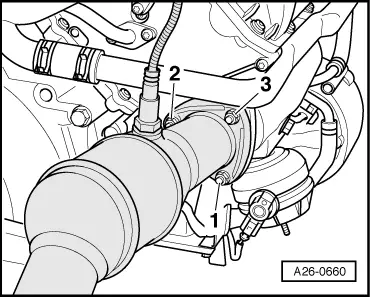
| Component | Nm |
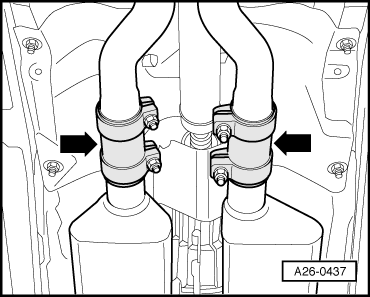
| Front exhaust pipe with starter and main catalytic converter to exhaust manifold | 27 |
| Front exhaust pipe with starter and main catalytic converter to mounting bracket | 25 |
| Push rod to gearbox | 40 |
| Connecting rod for selector rod to gearbox | 23 |
| Shield for drive shaft to gearbox | 23 |