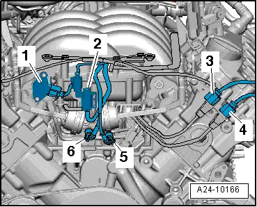
| Fitting locations in engine compartment |
| 1 - | Intake manifold flap potentiometer -G336- |
| 2 - | Intake manifold flap valve -N316- |
| 3 - | Electrical connector “brown” for knock sensor 4 -G199- |
| 4 - | Electrical connector “black ” for knock sensor 3 -G198- |
| 5 - | Electrical connector “brown” for knock sensor 2 -G66- |
| 6 - | Electrical connector “black ” for knock sensor 1 -G61- |

WARNING | t
| The fuel system operates under high pressure. The pressure in the high-pressure part of the injection system must be reduced to a residual pressure prior to opening the system → Chapter. |
| t
| A clean cloth must then be wrapped around the connection and the residual pressure dissipated by carefully loosening the connection. |
| t
| Observe notes on procedure for disconnecting the battery → Rep. Gr.27. |
|
|
|
|
 Note
Note