
A4 Mk2
| Overview of fitting locations |
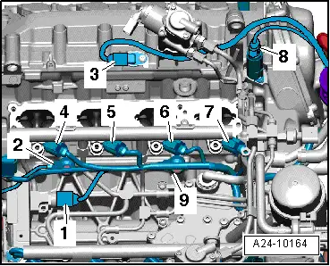
| Engine compartment (right-side) |

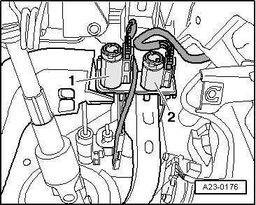
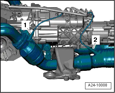
| 1 - | Secondary air pump motor -V101- |
| 2 - | Variable intake manifold change-over valve -N335- |
| 3 - | Hall sender 3 -G300- |
| q | Fitting location → Fig. |
| 4 - | Intake air temperature sender -G42- / air mass meter -G70- |
| 5 - | Exhaust camshaft control valve 1 -N318- |
| q | Fitting location → Fig. |
| 6 - | Lambda probe -G39- (before catalytic converter) |
| q | Fitting location → Fig. |
| q | Fitting location of connector → Fig. |
| q | Removing and installing → Chapter |
| 7 - | Lambda probe after catalytic converter -G130- |
| q | Fitting location → Fig. |
| q | Fitting location of connector → Fig. |
| q | Removing and installing → Chapter |
| 8 - | Camshaft control valve 1 -N205- |
| q | Fitting location → Fig. |
| 9 - | Engine control unit 2 -J624- |
| q | Fitting location → Fig. |
| 10 - | Coolant temperature sender -G62- |
| q | Fitting location → Fig. |
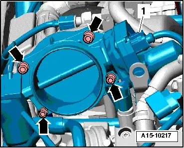
| 11 - | Throttle valve module -J338- |
| q | After renewing, perform adaption in “Guided Functions”, option “Adapt throttle valve module” |
| q | Fitting location → Fig. |
| 12 - | Knock sensor 2 -G66- |
| q | Fitting location → Fig. |
| q | Fitting location of connector → Fig. |
| q | 20 Nm |
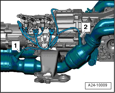
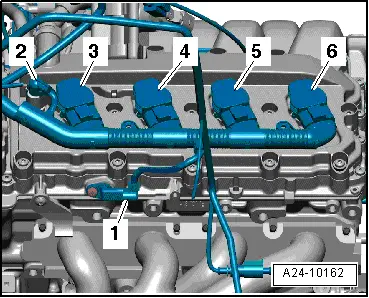
| 13 - | Injectors, cylinder bank 1 |
| q | Injector, cylinder 1 -N30- |
| q | Injector, cylinder 2 -N31- |
| q | Injector, cylinder 3 -N32- |
| q | Injector, cylinder 4 -N33- |
| q | Fitting location → Fig. |
| q | Removing and installing → Chapter |
| 14 - | Intake manifold flap valve -N316- |
| Fitting location → Fig. |
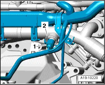
| 15 - | Fuel pressure sender -G247- |
| q | Fitting location → Fig. |
| 16 - | Intake manifold flap potentiometer -G336- |
| q | Fitting location → Fig. |
| q | Fitting location → Fig. |
| q | After renewing, perform adaption in “Guided Functions”, option “Adapt potentiometer for intake manifold flap (air flow control flaps)”. |
| 17 - | Knock sensor 1 -G61- |
| q | Fitting location → Fig. |
| q | Fitting location of connector → Fig. |
| q | 20 Nm |
| 18 - | Hall sender -G40- |
| q | Fitting location → Fig. |
| 19 - | High-pressure pump |
| q | With fuel metering valve -N290- |
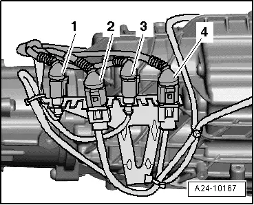
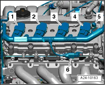
| 20 - | Ignition coils for cylinder bank 1 |
| q | Ignition coil 1 with output stage -N70- |
| q | Ignition coil 2 with output stage -N127- |
| q | Ignition coil 3 with output stage -N291- |
| q | Ignition coil 4 with output stage -N292- |
| q | Fitting location → Fig. |
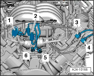
| Engine compartment (left-side) |

| 1 - | Fuel pressure sender for low pressure -G410- |
| 2 - | Intake manifold flap potentiometer 2 -G512- |
| q | After renewing, perform adaption in “Guided Functions”, option “Adapt potentiometer for intake manifold flap (air flow control flaps)”. |
| 3 - | Activated charcoal filter solenoid valve 1 -N80- |
| 4 - | Brake servo pressure sensor -G294- |
| 5 - | Engine speed sender -G28- |
| q | Fitting location → Fig. |
| 6 - | Camshaft control valve 2 -N208- |
| q | Fitting location → Fig. |
| 7 - | Fuel metering valve 2 -N402- |
| 8 - | Lambda probe 2 after catalytic converter -G131- |
| q | Fitting location → Fig. |
| q | Fitting location of connector → Fig. |
| q | Removing and installing → Chapter |
| 9 - | Engine fault warning lamp |
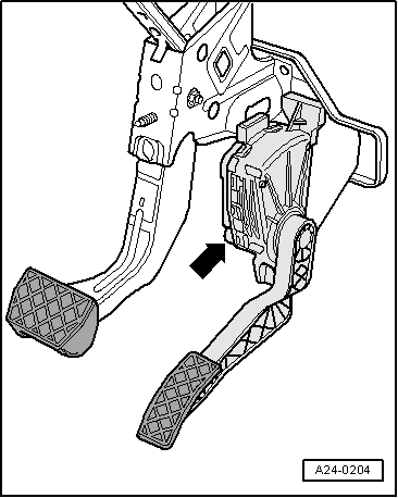
| 10 - | Accelerator position sender -G79- and accelerator position sender 2 -G185- |
| q | In accelerator pedal module; fitting location → Fig. |
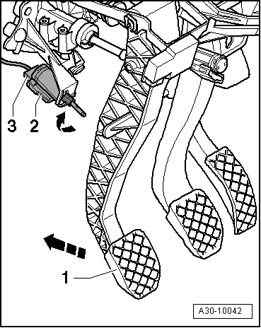
| 11 - | Brake light switch -F-/brake pedal switch -F47- |
| q | Fitting location → Fig. |
| 12 - | Clutch pedal switch for engine start -F194- and clutch pedal switch -F36- |
| q | Fitting location of clutch pedal switch -F36- → Fig. |
| q | Fitting location of clutch pedal switch for engine start -F194- → Fig. |
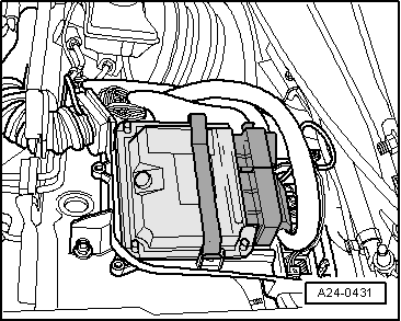
| 13 - | Electronics box, plenum chamber |
| q | With engine control unit -J623- |
| q | Fitting location → Fig. |
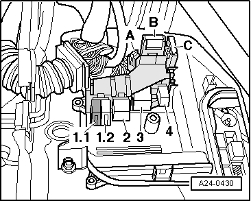
| q | With 4-position relay carrier for brake servo relay -J569-, Motronic current supply relay -J271-, engine component current supply relay -J757-, secondary air pump relay -J299- |
| q | Fitting locations → Fig. |
| 14 - | Lambda probe 2 -G108- (before catalytic converter) |
| q | Fitting location → Fig. |
| q | Fitting location of connector → Fig. |
| q | Removing and installing → Chapter |
| 15 - | Exhaust camshaft control valve 2 -N319- |
| q | Fitting location → Fig. |
| 16 - | Brake vacuum pump -V192- |
| 17 - | Continued coolant circulation pump -V51- |
| q | Fitting location → Fig. |
| 18 - | Hall sender 4 -G301- |
| q | Fitting location → Fig. |
| 19 - | Ignition coils for cylinder bank 2 |
| q | Ignition coil 5 with output stage -N323- |
| q | Ignition coil 6 with output stage -N324- |
| q | Ignition coil 7 with output stage -N325- |
| q | Ignition coil 8 with output stage -N326- |
| q | Fitting location → Fig. |
| 20 - | Hall sender 2 -G163- |
| q | Fitting location → Fig. |
| 21 - | Knock sensor 4 -G199- |
| q | Fitting location → Fig. |
| q | 20 Nm |
| 22 - | Knock sensor 3 -G198- |
| q | Fitting location → Fig. |
| q | 20 Nm |
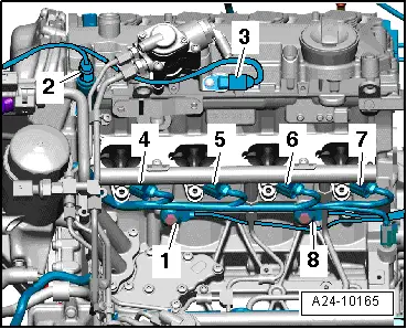
| 23 - | Injectors, cylinder bank 2 |
| q | Injector, cylinder 5 -N83- |
| q | Injector, cylinder 6 -N84- |
| q | Injector, cylinder 7 -N85- |
| q | Injector, cylinder 8 -N86- |
| q | Fitting location → Fig. |
| q | Removing and installing → Chapter |
| 24 - | Secondary air inlet valve -N112- |
| q | Fitting location → Fig. |
|
|
|
|
 Note
Note
|
|
Note
|
|
|
|
|
|
|
|
|
|
|
|
|
|
|
|
|
|
|
|
|
|
|
|
|
|
|
|
|
|