
A4 Mk2
|
|
|
 Note
Note
|
|
|
|
 Caution
|
|
|
|
|
|
 WARNING
|
|
|
|
Note |
|
|
|
Note
|
|
|
|
|
|
|
|
|
|
Note
|
|
|
|
Note
Note
|
|
|
|
Note
|
|
Note
|
|
Note |
|
|
|
|
|
|
|
|
|
Note
|
|
|
|
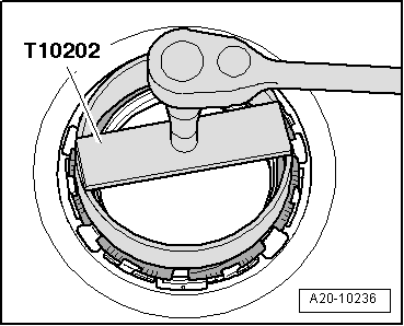
| Component | Nm |
| Locking ring for fuel delivery unit or flange of fuel gauge sender 2 -G169- | 145 |