
A4 Mk2
| Removing and installing subframe |

| Special tools and workshop equipment required |
| t | Support bracket -10 - 222 A- |
| t | Rack -10 - 222 A /1- |
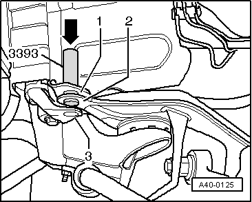
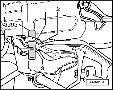
| t | Mandrels -3393- |
| t | Torque wrench -V.A.G 1331- |
| t | Torque wrench -V.A.G 1332- |
| t | Engine and gearbox jack -V.A.G 1383 A- |
|
|
|
|
|
|
|
|
|
|
|
|
|
 Note
Note
|
|
|
|
|
|
|
|
Note
|
|
|
|
|
|
|
|
Note
|
|
|
|
|
|
|
|
|
|
Note
|
|