audi Workshop Repair Guides

Audi Workshop Service and Repair Manuals

Rear subframe > < General information
Removing and installing trapezium link
Special tools and workshop equipment required
t  Torque wrench -V.A.G 1331-
t  Torque wrench -V.A.G 1332-
Removing
–  Remove underbody trim in front of trapezium link.
   
Cabriolet models only
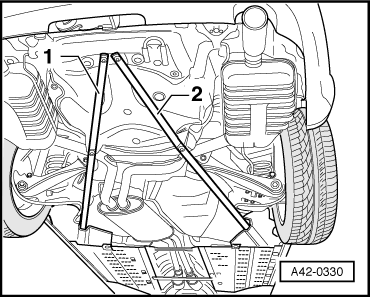
–  Remove diagonal struts -1- and -2- → Chapter.
All vehicles (continued):
–  Remove coil spring → Chapter.
Vehicles with heavy-duty suspension
–  Remove stone deflector from trapezium link.
All vehicles (continued):
–  Loosen bolts and detach handbrake cable from bracket below trapezium link.
  A42-0330
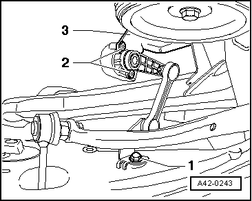
–  On vehicles with headlight range control, remove bolt -1-.
  A42-0243
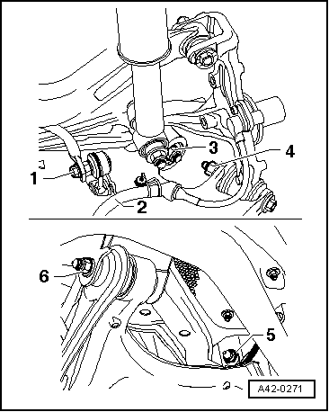
–  Detach wiring guide for speed sensor -2- → Fig..
–  Remove bolt -1-. Counterhold joint with open-end spanner.
–  Mark position of eccentric bolt -5- on subframe.
–  Detach trapezium link (items 3 to 6).
  Note
On vehicles with four-wheel drive and for the right trapezium link on vehicles with front-wheel drive, the subframe must be lowered slightly in order to remove the bolts.
Vehicles with four-wheel drive
–  Unbolt propshaft from rear final drive. → Rear final drive 01R; Rep. Gr. 39; Servicing propshaft; Removing and installing propshaft
–  Secure propshaft to body with wire.
–  Unbolt shock absorber from wheel bearing housing.
–  Detach handbrake cables from fuel tank.
–  Detach brake caliper → Brake system; Rep. Gr. 46; Servicing brake caliper
–  Detach heat shield from right drive shaft (when removing right-side trapezium link).
–  Lower subframe slightly → Chapter.
Removing left-side trapezium link (vehicles with front-wheel drive)
–  Detach heat shield in front of eccentric bolt from body and push to the side.
Removing right-side trapezium link (vehicles with front-wheel drive)
–  Unbolt shock absorber from wheel bearing housing.
–  Detach brake caliper → Brake system; Rep. Gr. 46; Servicing brake caliper
–  Lower subframe slightly → Chapter.
  A42-0271
All vehicles (continued):
–  Detach trapezium link (items 3 to 6).
  Note
Ensure that subframe is supported firmly.
Installing
Renew bolts and self-locking nuts ⇒ instructions in exploded views from → Chapter onwards.
–  Install subframe → Chapter.
–  Install shock absorber → Chapter.
–  Install brake caliper. → Brake system; Rep. Gr. 46; Rear brakes type C38; Servicing brake caliper
–  Bolt propshaft to rear final drive. → Rear final drive 01R; Rep. Gr. 39; Servicing propshaft; Removing and installing propshaft
–  Install heat shield for drive shaft → Item.
Bonded rubber bushes can only be turned to a limited extent. The mountings of the suspension links must therefore only be tightened when the suspension is in the unladen position → Chapter.
  A42-0271
–  Tighten bolt connections -3-, -4- and -6- → Chapter.
–  Tighten nut -5- (set eccentric bolt to its original position) → Item.
–  Install wiring guide for speed sensor -2- → Fig..
–  Tighten bolt -1- → Item.
–  Install coil spring → Chapter.
–  Attach handbrake cable at bracket.
  A42-0271
–  On vehicles with headlight range control, tighten bolt -1- → Item, → Item.
–  Check and adjust wheel alignment → Chapter.
Wheel alignment must always be checked and adjusted if necessary using VW/Audi-approved equipment.
Vehicles with heavy-duty suspension
–  Install stone deflector and tighten bolts → Item.
  A42-0243
Cabriolet models only
–  Install diagonal struts -1- and -2- → Chapter.
All vehicles (continued):
–  Install underbody trim.
  A42-0330

Rear subframe > < General information