audi Workshop Repair Guides

Audi Workshop Service and Repair Manuals

Removing and installing bearing for torsion bar > < Exploded view of torsion bar
Removing and installing torsion bar
Special tools and workshop equipment required
   
t  Extension -2024 A /1-
  W00-0568
t  Counterhold tool -3145-
t  Shackle Ø 8 mm (commercially available)
t  M10x30 bolt and nut
Removing
  WARNING
t  Observe safety regulations for pyrotechnic components → Chapter.
t  Before handling pyrotechnic components (e.g. unplugging the electrical connector) the mechanic must discharge static electricity by briefly touching the door striker plate, or similar.
  Caution
Move front seat to top position if possible. This will reduce the spring force when removing and installing the torsion bar and minimise the risk of damage to the bolt fittings between the seat pan upper and lower frame.
–  Remove front seat:
t  Standard seat and sports seat (with manual adjustment) → Chapter „Removing and installing front standard seat (with manual adjustment)“.
t  Standard seat, sports seat (with electric adjustment), convenience seat and super sports seat → Chapter „Removing and installing front standard seat (with electric adjustment)“.
–  Attach front seat to seat repair stand -VAS 6136- → Chapter.
–  Remove trim (sill side):
t  Standard seat and sports seat (with manual adjustment) → Chapter „Removing and installing trim (sill side)“.
t  Standard seat and sports seat (with electric adjustment), and convenience seat → Chapter „Removing and installing trim (sill side)“.
–  Remove trim (tunnel side) → Chapter.
–  Remove front seat backrest → Chapter.
  W00-0029
–  Slacken bolt connection -3- for belt buckle (front) -1-.
–  Swivel belt buckle (front) downwards.
The electrical wire does not need to be unplugged or removed.
  WARNING
The torsion bar exerts a considerable spring force. To avoid accidents, it is important that you observe the following points:
t  Always remove and install the torsion bar in the sequence described, and use only the specified tools.
t  Never use pliers or other levering aids.
t  Do not stand directly in front of the torsion bar when removing and installing it, but off to the side.
  A69-10404
–  Secure counterhold tool -3145- to torsion bar -3- with extension -2024 A /1- and shackle -2- (as shown).
1 - M10x30 bolt with nut
4 - Seat pan
  A72-10820
–  Carefully rotate torsion bar -1- until it can be detached from slot -arrow- in seat pan.
–  Pull torsion bar out of seat pan -2- with extension -2024 A /1-.
Installing
  WARNING
The torsion bar exerts a considerable spring force. To avoid accidents, it is important that you observe the following points:
t  Always remove and install the torsion bar in the sequence described, and use only the specified tools.
t  Never use pliers or other levering aids.
t  Do not stand directly in front of the torsion bar when removing and installing it, but off to the side.
  A72-10831
–  Push torsion bar -1- into mounting until end -arrow- makes contact with seat pan -2-.
  A72-10832
–  Make sure torsion bar -2- is positioned correctly in support bracket -arrow- of seat pan -1-.
  A72-10833
–  Apply counterhold tool -3145- at torsion bar -1- with extension -2024 A /1- and bolt connection -3-, but without shackle.
2 - Seat pan
  A72-10834
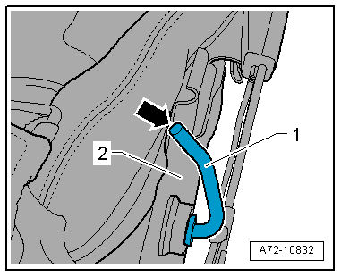
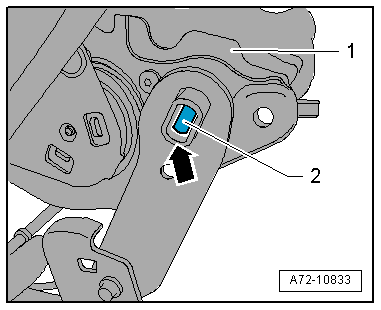
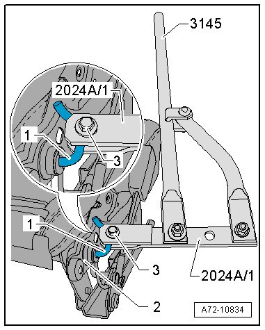
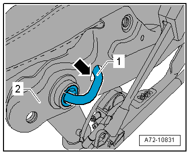
–  Rotate torsion bar -1- and carefully push it until it can be engaged in slot -arrow- in seat pan -2-.
Perform remaining installation steps in reverse order of removal; observe the following:
  WARNING
t  Observe safety regulations for pyrotechnic components → Chapter.
t  
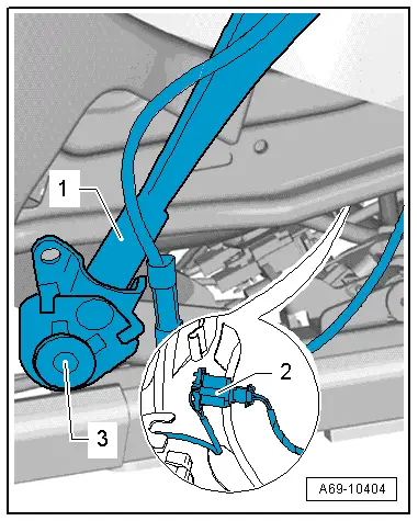
Before handling pyrotechnic components (e.g. plugging in the electrical connector) the mechanic must discharge static electricity by briefly touching the door striker plate, or similar.
  Note
Make sure electrical connectors are fitted correctly (as far as stop) and engage audibly.
  WARNING
The battery must be connected with the ignition switched on. If pyrotechnic components (e.g. airbag or belt tensioner) are inexpertly repaired, this may result in unwanted triggering after connecting the battery. There must not be anyone in the vehicle while you are connecting the battery.
–  With ignition switched on, connect battery earth wire → Electrical system; Rep. gr.27.
  Note
If the airbag warning lamp -K75- indicates a fault following installation, you must interrogate, erase and then re-interrogate the event memory → Vehicle diagnostic tester.
  A72-10831

Removing and installing bearing for torsion bar > < Exploded view of torsion bar