audi Workshop Repair Guides

Audi Workshop Service and Repair Manuals

Removing and installing footwell flap control motorV261 / left footwell flap control motorV108 > < Removing and installing defroster flap control motorV107
Removing and installing left centre vent control motorV110
Removing and installing left centre vent control motor -V110-
  Note
t  The left centre vent control motor -V110- is only fitted on vehicles with an air conditioner of the „Deluxe“ type.
t  At present all the control motors on this vehicle are identical. During basic setting, control motor assignment and adaption are implemented on the basis of the arrangement in the series connection of the wiring. If the sequence is not as specified, the matching of the control motors and thus flap control will not be correct → Chapter (block diagram of air conditioner control motors).
t  Removing and installing left mounting plate with control motors -V108- and -V110- → Chapter
t  Different versions of the levers and connecting elements are fitted at the air conditioning unit depending on the production period → Chapter and → Electronic parts catalogue.
Removing
–  Move the driver's seat to the rearmost position.
–  Switch off the ignition.
–  Remove the storage compartment beneath the dash panel on the driver side → General body repairs, interior; Rep. gr.70.
–  Remove the left (driver side) footwell vent → Chapter.
–  Remove the accelerator pedal module → Brake system; Rep. gr.46.
  Note
   
t  For greater clarity, the following illustrations show the position of the control motor and the mounting plate for this control motor on the left of the air conditioning unit with the air duct to the left dash panel vent -A- removed.
t  The air duct to the left dash panel vent -A- is attached with an expanding clip or a bolt -B- to the dash panel cross-member -C-. This expanding clip or bolt can only be removed after taking out the dash panel fascia.
–  Carefully unfasten the air duct to the left dash panel vent -A- from the vent of the air conditioning unit.
  A87-10514
–  Mark the connector -D- (to prevent interchange if several connectors are simultaneously unplugged).
–  Unplug the connector -D-.
–  Remove the bolts -C-.
  Note
The bolts -C- can also be removed using the ratchet ring spanner -T40083-.
–  Press the cam plate -E- towards the air conditioning unit and detach the shaft -A- (of the control motor -B-) from the cam plate -E-.
  Note
t  The left centre vent control motor -V110- actuates the connecting rod -F- (and thus the left indirect ventilation flap) by way of the cam plate -E- and the centre left dash panel vent flap via the lever -G-. If the pin of the lever -G- is released from the guide slot of the cam plate -E- on removing the control motor, the centre left dash panel vent flap is not actuated.
  A87-10495
t  On right-hand drive vehicles, the cam plate -E- is not driven directly by way of the shaft of the control motor -B-. With such vehicles, the cam plate -E- is actuated by way of two additional gear wheels -A- and -C-.
t  In Model Year 2008 modified gear wheels -A- and appropriately adapted holders (modified collar at gear wheel and an adapted hole) were gradually introduced. Attention is to be paid to correct assignment of the gear wheel to the holder (these components are included in the scope of delivery of the replacement part) → Electronic parts catalogue.
t  The connecting rod -F- actuates the flap in the left centre vent.
Installing
Install in reverse order; paying attention to the following:
  A87-10574
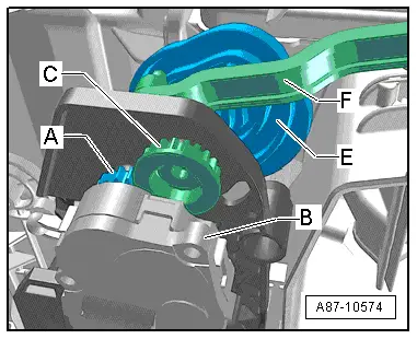
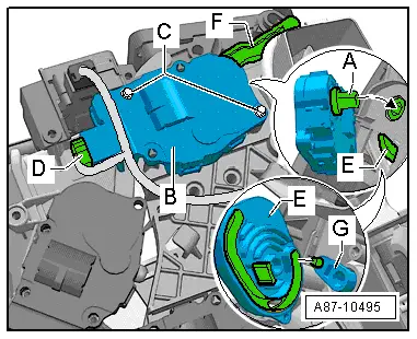
–  Check the pin of the lever -G- and the pin of the connecting rod -F- for correct positioning in the corresponding guide slot of the cam plate -E-.
–  Insert the shaft -D- of the control motor -B- in the cam plate -E-.
  Note
The control motor has no stop. The shaft of the control motor can thus be inserted in any position in the cam plate -E-.
–  Fit the bolts -C-.
–  Plug in the connector -D-.
–  Lay the wiring harness such that it cannot come into contact with moving components (e.g. lever).
–  Re-install all the other parts removed in reverse order.
–  Switch on the ignition.
–  Perform air conditioner basic setting and final control diagnosis → "Guided fault-finding" function of vehicle diagnostic, testing and information system VAS 5051.
  Note
t  The control motors on this vehicle are equipped with electronics. A new control motor only learns its position at the air conditioning unit in the course of basic setting and can then be actuated by the air conditioner operating and display unit, Climatronic control unit -J255- (all control motors are identical at present) → "Guided fault-finding" function of vehicle diagnostic, testing and information system VAS 5051.
t  During basic setting, control motor assignment and adaption are implemented on the basis of the arrangement in the series connection of the wiring. If the sequence is not as specified, the matching of the control motors and thus flap control will not be correct → Chapter (block diagram of air conditioner control motors).
–  Interrogate the event recorder of the air conditioner operating and display unit, Climatronic control unit -J255- and erase any faults displayed → "Guided fault-finding" function of vehicle diagnostic, testing and information system VAS 5051.
  A87-10495

Removing and installing footwell flap control motorV261 / left footwell flap control motorV108 > < Removing and installing defroster flap control motorV107