audi Workshop Repair Guides

Audi Workshop Service and Repair Manuals

Incorporation of auxiliary heater into coolant circuit > < Checking CO2 content in exhaust gas of auxiliary heater
Checking CO2 content
Special tools and workshop equipment required
t  Vehicle diagnostic, testing and information system -VAS 5051/-
t  Diagnostic wire -VAS 5051/5A-
t  Exhaust emission test station -VAS 6300-
t  Battery charger -VAS 5903-
–  With the ignition switched off, connect up the vehicle diagnostic, testing and information system -VAS 5051/- with the diagnostic wire -VAS 5051/5A- to the diagnostic connection in the vehicle → Vehicle diagnostic, testing and information systemVAS 5051/, “Guided fault-finding function”.
–  Connect up a battery charger, switch on ignition (and switch off all electrical equipment).
Or
–  Start engine (and switch off all electrical equipment).
  Note
Auxiliary heater guided fault-finding can only be started with the ignition switched on (the data bus diagnostic interface -J533- is only active when the ignition is on). Once the auxiliary heater has switched to diagnosis mode, auxiliary heater guided fault-finding can be continued even with the ignition switched off.
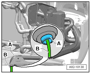
–  Select the address word “supplementary/auxiliary heater” → Vehicle diagnostic, testing and information systemVAS 5051/, “Guided fault-finding function”.
–  Interrogate the event recorder and eliminate any faults displayed → Vehicle diagnostic, testing and information systemVAS 5051/, “Guided fault-finding function”.
–  Erase the event recorder if applicable → Vehicle diagnostic, testing and information systemVAS 5051/, “Guided fault-finding function”.
  Note
The following illustration shows the positions of the components on an Audi A5 Coupé. The layout differs slightly on the Audi A4 and Audi Q5. On these other vehicles the work is however to be performed in the same manner as described for the Audi A5 Coupé.
   
–  Switch on the exhaust emission test station -VAS 6300- and insert the exhaust probe -B- in the exhaust pipe -A- of the auxiliary heater.
  WARNING
When pulling out the exhaust probe, take care not to touch the exhaust probe of the exhaust emission test station -VAS 6300- or the exhaust pipe as these become very hot.
  Note
t  The CO2 test does not involve removing the right wheel housing liner or the noise insulation.
t  The hose -B- of the exhaust probe must not stop exhaust gas emerging from the exhaust pipe -A- during the test.
–  Set the operating and display unit, Climatronic control unit -J255- to maximum heat output (“HI” temperature setting).
–  Restrict the fresh air blower speed by setting the operating and display unit to approx. 50 % of the maximum fresh air blower speed.
–  Switch on the auxiliary heater via the MMI (Multi Media Interface) → Chapter or e.g. by way of the vehicle diagnostic, testing and information system (“Basic setting” function) → Vehicle diagnostic, testing and information systemVAS 5051/, “Guided fault-finding function”.
–  Wait until the auxiliary heater switches from starting to full load mode (approx. 4 minutes).
  Note
t  The current operating status of the auxiliary heater can be seen from the measured value block → Vehicle diagnostic, testing and information systemVAS 5051/, “Guided fault-finding function”.
t  Unplugging the connector at the heater coolant shut-off valve -N279- causes the engine to be heated as well and the auxiliary heater operates for longer in full load mode.
–  Once the auxiliary heater has switched to full load mode, wait at least another 1 minute (approx. 4 minutes after activation, the auxiliary heater must be in full load mode).
–  Read off the measured value for the CO2 (carbon dioxide) content of the exhaust gas from the CO2 analyser.
  Note
  A82-10130
The hose -B- of the exhaust probe must not stop exhaust gas emerging from the exhaust pipe -A- during the test.
Specifications:
t  8 to 11 % by vol. CO2 for vehicles with diesel engine
t  7.5 to 10.5 % by vol. CO2 for vehicles with petrol engine
  Note
t  If the measured value is in the lower range (less than 9 % for diesel or less than 8.5 for petrol), problems may be encountered with auxiliary heater combustion under unfavourable usage conditions (e.g. high vehicle speed with auxiliary heater switched on). Check the fuel delivery rate of the metering pump -V54- → Chapter.
t  If the CO2 values displayed by the analyser only fluctuate slightly, form the mean value from the highest and lowest measured value.
t  If the measured values displayed for CO2 fluctuate considerably (more than approx. + / - 0.6 % depending on the analyser), check the position of the measurement probe in the auxiliary heater exhaust pipe.
–  If applicable, plug the connector back in at the heater coolant shut-off valve -N279-.
–  Interrogate and if necessary erase the event recorder → Vehicle diagnostic, testing and information systemVAS 5051/, “Guided fault-finding function”.
If the measured value is outside the permitted range:
–  Check the intake air noise insulation and the auxiliary heater exhaust system for contamination or cross-sectional constriction and clean or replace these components if necessary → Chapter and → Chapter.
–  Check the fuel delivery rate of the metering pump -V54- → Chapter.
–  If the CO2 content of the exhaust gas and the fuel delivery rate of the metering pump -V54- are in the lower specified range, replace the metering pump -V54- → Chapter.
If the CO2 content of the exhaust gas is not OK although the fuel delivery rate is:
–  Check the intake air noise insulation and the auxiliary heater exhaust system for contamination or cross-sectional constriction and clean or replace these components if necessary → Chapter and → Chapter.
If the CO2 content of the exhaust gas is not OK and no fault can be found:
–  Check the combustion air blower -V6- → Vehicle diagnostic, testing and information systemVAS 5051/, “Guided fault-finding function” and → Chapter.
In the event of auxiliary heater starting problems despite a correct fuel delivery rate and CO2 content in the exhaust gas:
–  Check the glow plug for heater -Q9- and the fuel pre-heating heater element -Z66- → Vehicle diagnostic, testing and information systemVAS 5051/, “Guided fault-finding function” and → Chapter.
  A82-10130

Incorporation of auxiliary heater into coolant circuit > < Checking CO2 content in exhaust gas of auxiliary heater