
A4 Mk3
| Exploded view - output shaft |
| Exploded view - removing and installing selector fork cluster, input shaft, 1st, 2nd and reverse gears on output shaft → Chapter |
| Dismantling and assembling output shaft → Chapter |
 Note
Note| t | Refer to technical data when installing new gears or output shaft → 6-speed manual gearbox 0B1, front-wheel drive; Rep. gr.00. |
| t | Lubricate all needle bearings and synchro-rings with gear oil before installing. |
| t | When renewing synchro-rings, renew inner ring, intermediate ring and synchro-ring for the corresponding gear together. |
| t | If synchro-rings are not being renewed, make sure they are re-installed on the same gear. |
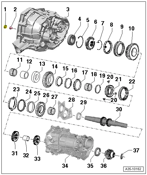
| 1 - | Sealing cap |
| q | With oil guide |
| q | For output shaft |
| q | Removing and installing → Chapter |
| 2 - | Bolt |
| q | 200 Nm |
| q | For output shaft |
| q | Apply locking fluid -AMV 185 101 A1- when fitting |
| q | To loosen, heat bolt to approx. 80 °C if necessary using hot air blower -V.A.G 1416- |
| 3 - | Gearbox housing |
| 4 - | Ball bearing |
| q | For output shaft |
| q | Removing and installing → Item |
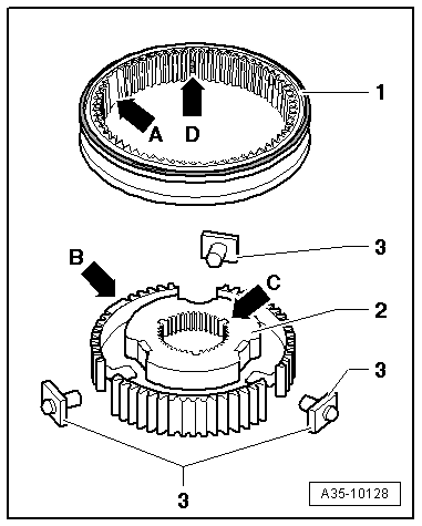
| 5 - | Circlip |
| q | Note installation position → Fig. |
| 6 - | Reverse gear synchro-hub |
| q | Removing and installing → Chapter |
| 7 - | Synchro-spring |
| q | Insert in drilling in reverse gear synchro-hub |
| 8 - | Synchro-ring for reverse gear |
| q | Checking for wear → Fig. |
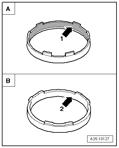
| 9 - | Reverse gear locking collar |
| q | Installation position → Fig. |
| 10 - | Reverse selector gear |
| q | Installation position → Fig. |
| 11 - | Needle bearing |
| q | For reverse gear |
| 12 - | Needle bearing inner race |
| q | For reverse gear |
| q | Removing and installing → Chapter |
| 13 - | Thrust washer |
| q | For 1st speed and reverse selector gears |
| 14 - | 1st speed selector gear |
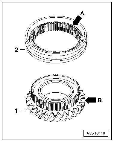
| 15 - | Inner ring for 1st gear |
| q | Installation position → Fig. |
| q | Distinguishing inner rings for 1st and 2nd gear → Fig. |
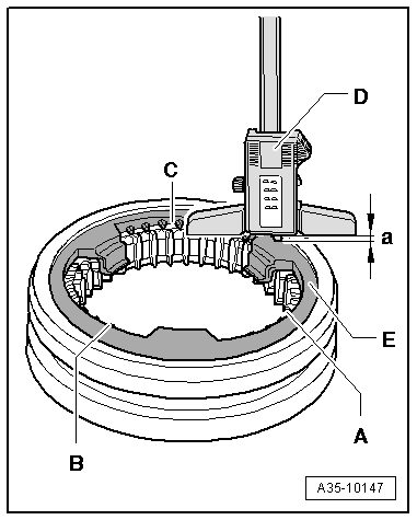
| q | Checking for wear → Fig. |
| q | Renew if scored or if there are visible traces of wear |
| 16 - | Intermediate ring for 1st gear |
| q | Installation position → Fig. |
| q | Checking for wear → Fig. |
| 17 - | Synchro-ring for 1st gear |
| q | Installation position → Fig. |
| q | Checking for wear → Fig. |
| q | Renew if scored or if there are visible traces of wear |
| 18 - | Needle bearing |
| q | For 1st gear |
| 19 - | Circlip |
| q | Determining thickness → Anchor |
| 20 - | Thrust block |
| q | 3x |
| q | Installing → Fig. |
| 21 - | Synchro-hub for 1st and 2nd gear |
| q | Installation position → Fig. |
| 22 - | Locking collar for 1st and 2nd gear |
| q | Installation position → Fig. |
| 23 - | Synchro-ring for 2nd gear |
| q | Installation position → Fig. |
| q | Checking for wear → Fig. |
| q | Renew if scored or if there are visible traces of wear |
| 24 - | Intermediate ring for 2nd gear |
| q | Installation position → Fig. |
| q | Checking for wear → Fig. |
| 25 - | Inner ring for 2nd gear |
| q | Installation position → Fig. |
| q | Distinguishing inner rings for 1st and 2nd gear → Fig. |
| q | Renew if scored or if there are visible traces of wear |
| 26 - | 2nd speed selector gear |
| 27 - | Needle bearing |
| q | For 2nd gear |
| 28 - | Bearing mounting |
| q | Carries bearings for input shaft and output shaft in gearbox cover |
| q | → Item |
| 29 - | Roller bearing |
| q | For output shaft |
| q | Pressing off → Fig. |
| q | Pressing on → Fig. |
| q | Always renew |
| 30 - | Output shaft |
| q | With splines for 5th and 6th gear |
| 31 - | 3rd gear wheel |
| q | Pressing off → Fig. |
| q | Installation position: high inside collar faces 4th gear |
| q | Pressing on → Fig. |
| 32 - | Spacer sleeve |
| 33 - | 4th gear wheel |
| q | Pressing off → Fig. |
| q | Installation position: high inside collar faces spur gear → Item |
| q | Pressing on → Fig. |
| 34 - | Gearbox cover |
| 35 - | Roller bearing |
| q | Bearing for spur gear in gearbox cover |
| q | Removing and installing → Item |
| 36 - | Spur gear |
| q | Drive gear for side shaft / pinion shaft (spur gearing) |
| q | Removing and installing → Chapter |
| 37 - | Circlip |
| q | Determining thickness → Anchor |
| q | Fit in annular groove on output shaft |
|
|
|
|
|
|
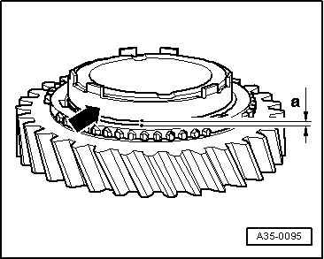
| Gap -a- | Wear limit |
| Inner ring for 1st gear | 0.6 mm |
Note
|
|
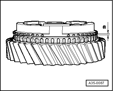
| Gap -a- | Wear limit |
| 1st and 2nd gear | 0.7 mm |
Note
|
|
|