A4 Mk3
| Exploded view - servicing gearbox housing |

| Special tools and workshop equipment required |
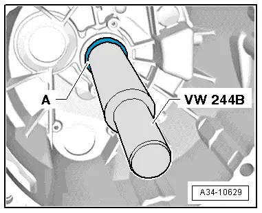
| t | Drift sleeve -VW 244 B- |
| t | Multi-purpose tool -VW 771- |
| t | Mandrel -30 - 505- |
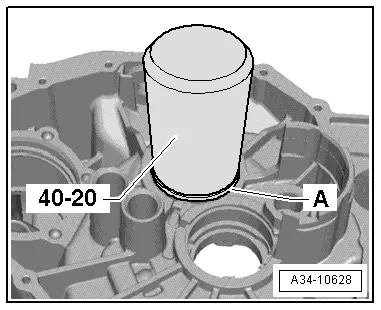
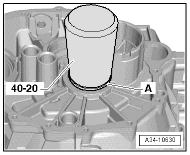
| t | Drift sleeve -40 - 20- |
| t | -1-Internal puller -Kukko 21/3- |
| t | Lubricating paste -G 000 150- |
 Note
Note| t | At present there is no provision for dismantling and assembling the differential. |
| t | At present there is no provision for removing and installing the pinion shaft. |
| t | At present there is no provision for adjusting the pinion shaft and crown wheel. |
| t | Replacement: renew gearbox housing together with installed pinion shaft and differential. |

| 1 - | Intermediate piece |
| q | Renew if damaged |
| 2 - | Ball-head pin |
| q | 25 Nm |
| q | Grease bearing surface for clutch release lever with lubricating paste -G 000 150- |
| 3 - | Cap |
| q | For gearbox breather |
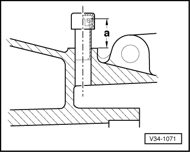
| 4 - | Breather pipe |
| q | Installation depth → Fig. |
| q | Clip in cap for gearbox breather |
| 5 - | Oil seal |
| q | For flange shaft (left-side) |
| q | Removing and installing → Chapter |
| 6 - | Differential |
| q | Can currently only be renewed together with gearbox housing and pinion shaft |
Note| Differential bevel gears cannot be removed and installed |
| 7 - | O-ring |
| q | Always renew |
| q | Lubricate with gear oil |
| 8 - | Cover for final drive |
| q | Renewing → Chapter |
| 9 - | Bolt |
| q | 20 Nm and then turn 90° further |
| q | Steel bolts (M8; 38 mm long) |
| q | 10x |
| 10 - | Flange shaft (right-side) |
| q | With circlip |
| q | Removing and installing → Chapter |
| 11 - | Oil seal |
| q | For flange shaft (right-side) |
| q | Removing and installing → Chapter |
| 12 - | Oil collector |
| 13 - | Pinion shaft |
| q | Can currently only be renewed together with gearbox housing and differential |
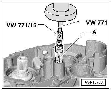
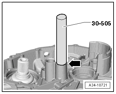
| 14 - | Bearing bush |
| q | For selector plate / selector fork |
| q | 3x |
| q | Removing → Fig. |
| q | Installing → Fig. |
| 15 - | Ball bearing |
| q | For output shaft |
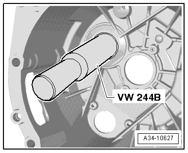
| q | Driving out → Fig. |
| q | Driving in → Fig. |
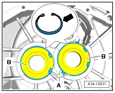
| 16 - | Circlip |
| q | Installation position → Fig. |
| 17 - | Circlip |
| q | Installation position → Fig. |
| 18 - | Ball bearing |
| q | For input shaft |
| q | Driving out → Fig. |
| q | Driving in → Fig. |
| 19 - | Magnet |
| q | Clean |
| 20 - | Oil drain plug |
| q | 45 Nm |
| 21 - | Gearbox housing |
| q | Can currently only be renewed together with differential and pinion shaft |
|
|
|
|
|
|
|
|
|
|
|
|
|
|