audi Workshop Repair Guides

Audi Workshop Service and Repair Manuals

Exploded view - centre differential housing > < Removing and installing input shaft, output shaft, reverse gear wheel and selector plates / selector forks
Assembly sequence - dismantling and assembling gearbox
Centre differential housing, centre differential, spur gears, gearbox cover, input shaft and output shaft are removed and installed together with internal gearbox selector mechanism.
  Note
t  The differential does not have to be removed in order to remove the above-mentioned components.
t  Refer to general repair instructions → Chapter.
   
Special tools and workshop equipment required
t  Drift sleeve -VW 244 B-
t  Thrust plate -40 -105-
t  Punch -3013-
t  Clamping sleeve -3116-
t  Puller -3349-
t  Extractor tool -T20143-

   
t  Assembly tool -T40041-
t  Thrust piece -T40174-
t  Gearbox support -T40206-
t  Separating tool -T40213-
t  Support -T40214-
t  Guide pin -T40216-

   
t  Hot air blower -V.A.G 1416-
t  Locking fluid -AMV 185 101 A1-
t  Sealing paste -AMV 188 001 02-
t  Grease for clutch plate splines -G 000 100-
t  Lubricating paste -G 000 150-
t  Sealing grease -G 052 128 A1-
Dismantling gearbox
  W00-0004
–  Place drip tray underneath.
–  Unscrew plug -arrow- and drain off gear oil.
  A34-10447
–  Attach gearbox support -T40206- to gearbox using bolts -arrows- and secure in assembly stand.
–  Remove clutch module → Chapter.
–  Put clutch module down carefully, e.g. on work bench.
  A34-10727
–  Remove clutch release lever -1- together with release bearing -2- and retaining spring -3-.
–  Remove bolts -4- and detach retaining piece -5- (if fitted) with guide sleeve -6-.
  A34-10723
–  If fitted, remove gearbox neutral position sender -G701--A-.
–  To do this, remove bolt -arrow- and pull sender out of sealing cap -B- for selector shaft.
  Note
t  Sealing cap -B- remains fitted.
t  If a sealing plug is fitted in place of the gearbox neutral position sender -G701-, it does not have to be removed when dismantling and assembling the gearbox.
  A34-10786
–  Remove bolts -1- and carefully lever off selector shaft cover -2-.
  A34-10461
–  Lift selector shaft slightly -arrow A- and pull it out -arrow B-.
  A34-10462
–  Lock input shaft and output shaft in position by moving selector plates -1- to -4- in direction of -arrow-.
  Note
To avoid damaging the gearbox cover, put a cloth in the aperture for the selector shaft between the tool and the housing.
  A34-10814
–  Pierce through centre of sealing cap -A- for output shaft and prise out in direction of -arrow-.
  A34-10593
–  Now unscrew bolt -A- from output shaft.
B - Hexagon key (12 mm)
C - Torque wrench
–  Then move selector plates to neutral position.
  A34-10815
–  Prise out input shaft oil seal.
  A39-10265
–  Then remove circlip -1- in front of ball bearing for input shaft.
–  Remove shim -2-.
  Note
t  If this circlip -1- cannot be removed, detach the centre differential housing first and knock the input shaft forwards using a rubber-headed hammer.
t  It is important that the shim -2- be removed before pressing out the gear cluster so that the shim does not slip into the groove for the circlip.
  A34-10812
–  Unscrew bolts -A- and -arrows- for centre differential housing -B- from gearbox cover.
  A34-10452
–  Carefully pull off centre differential housing -6-, together with spring -3-, shim -4- and dished spring -5-.
–  Detach centre differential -2- and bearing plate -1-.
  A34-10453
If bearing plate -1- remains behind in centre differential housing, proceed as follows:
–  Grip one of side ribs on bearing plate -1- with pliers and pull off in direction of -arrow A-.
–  While doing so, carefully tap alternate sides of housing -arrows B- with a rubber-headed hammer.
  Caution
Take care not to damage sealing surface!
  A34-10458
–  Remove circlip -1- and pull spur gear drive output gear -2- off pinion shaft.
–  Detach spacer sleeve -3- and spur gear drive input gear -4- from output shaft. At the same time also detach needle bearing for spur gear drive input gear.
  A34-10813
–  Then turn gearbox in assembly stand so that gearbox cover -D- faces upwards.
–  Remove bolts -A- securing bearing mounting, bolts -B- securing reverse shaft and bolts -C- securing gearbox cover -D- to gearbox housing -E-.
–  Detach gearbox cover -D-; note input shaft ball bearing (do not tilt gearbox cover when pulling it off).
  Note
Ball bearing on input shaft (rear) is a push fit in gearbox cover.
  A34-10816
–  Remove reverse gear wheel with reverse shaft -1-.
–  Detach oil collector -2- from bearing mounting -3--arrows A- and -arrow B-.
–  Detach magnet -4- and oil guide -5- from gearbox housing.
  A34-10817
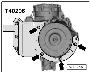
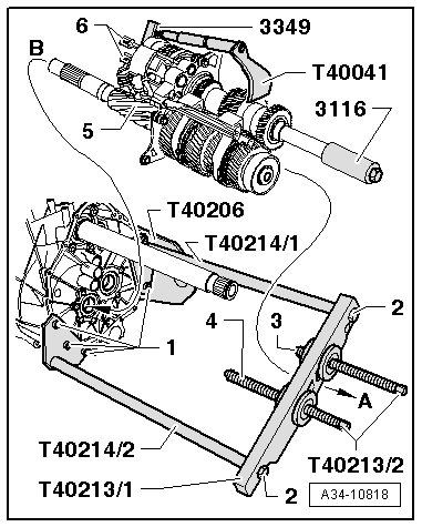
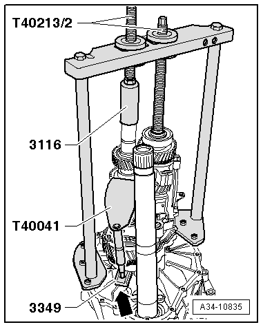
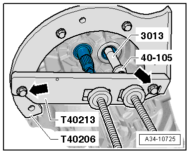
–  Attach separating tool -T40213- to gearbox support -T40206- with bolts -arrows-.
  Caution
Risk of damage to gears, shafts and bearings.
t  The input shaft and output shaft must be pressed out together.
t  It is permissible to turn the spindles alternately not more than one turn at a time when pressing out the shafts.
t  
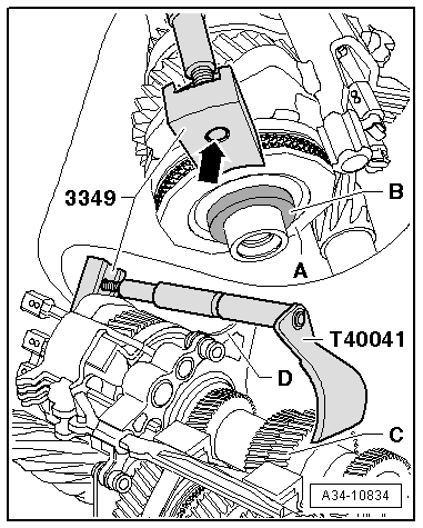
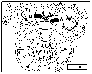
Make sure the synchromesh for the reverse gear does not slip off the output shaft when taking out the gear cluster.
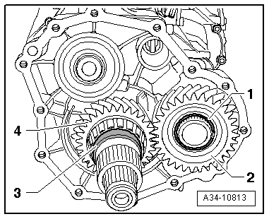
–  By turning spindles of separating tool -T40213- alternately one turn at a time, press input shaft and output shaft out of ball bearings in gearbox housing. While doing so, make sure gear cluster does not drop (get help from a second person if necessary).
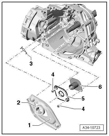
–  Detach input shaft and output shaft together with selector fork cluster from gearbox housing.
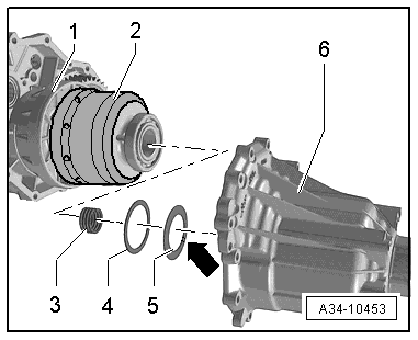
Assembling gearbox
  Note
If you are renewing the gearbox cover, spur gear drive input gear, tapered roller bearings for spur gear drive input gear, bearing plate or centre differential housing, you must first determine the thickness of the required shim for the preload of the tapered roller bearings for the spur gear drive input gear → Chapter.
  A34-10725
To prevent the synchromesh for the reverse gear from slipping apart when the gear cluster is inserted, these components must be secured as follows with an assembly tool:
–  Screw a hook of the puller -3349- onto assembly tool -T40041-, as shown in illustration.
–  Then position assembly tool with hook on reverse gear synchronising hub -A- and 3rd gear wheel -C- and tighten assembly tool.
l  Threaded spindle of assembly tool -T40041- must not protrude at hook-arrow-.
l  Assembly tool must be positioned within radius of bearing mounting -D-.
–  Fit thrust washer -B- with small amount of grease at reverse gear synchronising hub -A-.
  A34-10834
–  Fit clamping sleeve -3116- onto output shaft.
–  Secure supports -T40214/1- and -T40214/2- to gearbox housing, as shown in illustration, with bolts -1- (6x in total).
–  Attach plate -T40213/1- to supports -T40214/1- and -T40214/2- with bolts -2-.
–  Turn spindle -3- back as far as stop and set spindle -4- to central position.
–  Turn gearbox housing with mounted special tools so it is horizontal in assembly stand, as shown in illustration.
–  Heat ball bearings in gearbox housing with hot air blower -V.A.G 1416-.
–  First guide gear cluster -5- underneath plate -T40213/1- in direction of -arrow A-.
–  Then insert gear cluster with input shaft in gearbox housing (-arrow B-).
–  Hold gear cluster in this position and apply the two spindles -T40213/2- at shafts. Selector plates -6- must be aligned with bearing points in gearbox housing.
  Note
Depending on the fit between the ball bearings and the shafts, the gear cluster can be pressed all the way into the gearbox housing by hand on some gearbox versions.
  A34-10818
–  Then turn the gearbox in the assembly stand so that the gear cluster faces upwards.
–  If necessary, align spindles -T40213/2- with shafts again so that spindles press on shafts centrally.
  Caution
Risk of damage to gears, shafts and bearings.
t  The input shaft and output shaft must be pressed in together.
t  It is permissible to turn the spindles alternately not more than one turn at a time when pressing in the shafts.
–  Then, by turning spindles -T40213/2- alternately one turn at a time, press in input shaft and output shaft until they are seated in ball bearings.
  Note
t  Keep shafts straight while pressing them in. Guide selector plates into corresponding bearing points in gearbox housing.
t  Detach assembly tool -T40041- before hook comes into contact with housing rib -arrow-.
t  Note synchromesh for reverse gear. Tabs on intermediate ring must lock in reverse gear synchronising hub.
–  Detach separating tool -T40213- and supports -T40214-.
  A34-10835
–  Insert magnet -4- and oil guide -5- into gearbox housing.
–  Position oil collector -2- on pin -arrow B- of bearing mounting -3- and clip in at bearing mounting -arrows A-.
–  Install reverse gear wheel with reverse shaft -1- (align threaded hole -arrow C- with aperture -arrow D- for slave cylinder).
–  Check whether the two dowel sleeves for centring gearbox cover to gearbox housing are fitted in gearbox housing/gearbox cover.
–  Apply sealing paste -AMV 188 001 02- evenly and not too thickly onto contact surfaces between gearbox housing and gearbox cover.
  A34-10817
–  Position gearbox cover -D- on gearbox housing -E-; do not screw in bolts -C- yet.
–  Screw bolt -B- into reverse shaft (hand-tight).
–  Clean threads of bolts -A- with a wire brush. Then apply locking fluid -AMV 185 101 A1- and screw bolts hand-tight into bearing mounting.
–  Tighten bolts -C- to specified torque.
–  Then tighten bolts -A- and -B- to specified torque.
  A34-10816
–  Position shim -2- on input shaft.
Determining thickness of circlip -1- for input shaft
–  Determine the thickest circlip that will just fit and install it. For part number refer to → Electronic parts catalogue.
  Note
Start with the thickest circlip.
The following circlips are available:
  A34-10812
Circlip thickness (mm)
1.952.102.25
2.002.15 
2.052.20 

   
–  Fit spur gear drive input gear -4- with needle bearing → Item and spacer sleeve -3- on output shaft.
  Note
If you are renewing the gearbox cover, spur gear drive input gear or the centre differential, you must first determine the thickness of the shim required for adjusting the preload of the ball bearings of the centre differential → Chapter.
–  Position spur gear drive output gear -2- on pinion shaft and install circlip -1-.
  A34-10813
Install bearing plate -1- on gearbox cover as follows:
l  Installation position: lug -arrow A- on bearing plate -1- must engage in recess -arrow B- in gearbox cover.
  A34-10819
–  Slide on centre differential -2- towards bearing plate -1- as far as stop.
–  Fit dished spring -5-, shim -4- and spring -3- in centre differential housing -6-.
l  Installation position of dished spring -5-: inner diameter (convex side) -arrow- faces centre differential housing -6-.
–  Apply sealing paste -AMV 188 001 02- evenly and not too thickly.
–  Then fit centre differential housing -6- onto gearbox.
  A34-10453
–  Press centre differential housing -B- fully onto gearbox cover and hold in place.
–  Fit bolts -A- and new bolts -arrows- and tighten to specified torque.
  A34-10452
–  Lock input shaft and output shaft in position by moving selector plates -1- to -4- in direction of -arrow-.
  Note
To avoid damaging the gearbox cover, put a cloth in the aperture for the selector shaft between the tool and the housing.
  A34-10814
–  Tighten new bolt -A- securing output shaft to specified torque.
B - Hexagon key (12 mm)
C - Torque wrench
–  Then move selector plates to neutral position.
  A34-10815
–  Before installation, lightly oil outside circumference of new sealing cap -A- for output shaft, and drive in until flush.
  A34-10603
For gearboxes: Audi A5 Coupé 2008 ► up to gearbox serial number 000760
  Note
Gearboxes with these serial numbers were installed only in the Audi A5 Coupé 2008 ►.
–  Lightly oil outer circumference of new oil seal for input shaft.
–  Pack space between sealing lip and dust lip half-full with sealing grease -G 052 128 A1-.
–  Drive in new oil seal until flush (take care to keep seal straight).
  A39-10266
For gearboxes: Audi A4 2008 ►; Audi A5 Coupé 2008 ► from gearbox serial number 000761 onwards
–  Lightly oil outer circumference of new oil seal.
–  Pack space between sealing lip and dust lip half-full with sealing grease -G 052 128 A1-.
–  Drive in new oil seal onto stop using thrust piece -T40174-. Take care to keep seal straight when installing.
Continued for all gearboxes
–  Apply sealing paste -AMV 188 001 02- evenly and not too thickly onto sealing surface between selector mechanism cover and gearbox cover.
  A39-10328
–  Screw guide pin -T40216- onto selector shaft -1-.
  A34-10728
–  Lift selector shaft slightly -arrow B- and install it in gearbox -arrow A-.
  A34-10488
–  Selector shaft cover -2- must make contact with gearbox cover.
–  Clean threads of bolts -1- with wire brush. Then insert bolts with locking fluid -AMV 185 101 A1- and tighten to specified torque.
–  Unscrew guide pin -T40216-.
  A34-10461
–  If previously fitted, insert gearbox neutral position sender -G701--A- with new O-ring in sealing cap -B- for selector shaft.
–  Clean thread of bolt -arrow- with a wire brush. Then insert bolt with locking fluid -AMV 185 101 A1- and tighten to specified torque.
  A34-10786
–  Fit guide sleeve -6- and retaining piece -5-, if applicable.
–  Clean threads of bolts -4- with wire brush. Then install bolts with locking fluid -AMV 185 101 A1- and tighten to specified torque → Item.
  Caution
Grating/creaking noises can occur when clutch is operated.
l  Lack of grease at the bearings -2- on the release bearing assembly can cause creaking/grating noises when the clutch is operated.
l  Grease bearings on release bearing assembly thoroughly with lubricating paste -G 000 150- → Fig..
l  Remove grease in bearing surface for guide sleeve: bearing of release bearing on guide sleeve must be free of grease.
–  Install release lever -1- together with release bearing -2- and retaining spring -3- → Chapter.
–  Install clutch module and flange shaft (left-side) → Anchor.
–  Fill up with gear oil and check oil level in manual gearbox → 6-speed manual gearbox 0B4, four-wheel drive; Rep. Gr.34.
  A34-10723

Exploded view - centre differential housing > < Removing and installing input shaft, output shaft, reverse gear wheel and selector plates / selector forks