audi Workshop Repair Guides

Audi Workshop Service and Repair Manuals

Securing engine to assembly stand > < Installing radiators, condensers and charge air coolers
Removing engine
Removing engine
Special tools and workshop equipment required
   
t  Hose clip pliers -V.A.G 1921-
  W00-0464
t  Drip tray for workshop hoist -VAS 6208-
  W00-10228
t  Locking pin -T10060 A-
  W00-10235
t  Support bracket -10 - 222 A-
  W00-0225
t  Gearbox support -3147-
  W00-0566
t  Workshop hoist -VAS 6100-
  W00-1214
t  Lifting tackle -2024 A-
  W00-0224
t  Engine bung set -VAS 6122-
Procedure
  WARNING
Make sure the vehicle cannot tip over when the engine is removed.
Secure the vehicle, to do so, the luggage compartment must be empty.
  Note
t  Lift out engine without gearbox.
t  Collect drained coolant in a clean container for re-use or disposal.
t  Fit all cable ties in the original positions when installing.
t  On four-wheel drive vehicles the electromechanical parking brake must be released before disconnecting the battery, so that the propshaft can be turned during removal.
  Caution
To prevent irreparable damage to the electronic components when disconnecting the battery:
Observe notes on procedure for disconnecting the battery → Rep. gr.27.
–  Disconnect battery → Rep. gr.27.
–  Remove both front wheels.
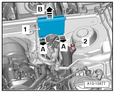
  WARNING
Hot steam/hot coolant can escape - risk of scalding.
t  The cooling system is under pressure when the engine is hot.
t  
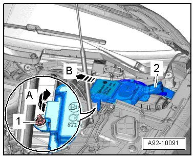
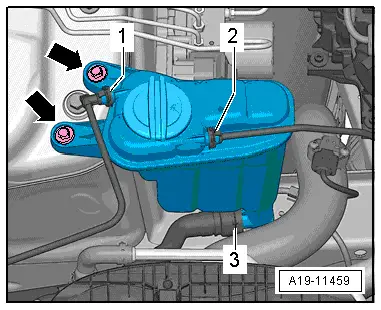
To allow pressure to dissipate, cover filler cap on coolant expansion tank with cloth and open carefully.
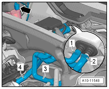
–  Open filler cap on coolant expansion tank.
–  Remove noise insulation → Rep. gr.66.
  W00-10435
–  Place drip tray for workshop hoist -VAS 6208- beneath engine.
–  Unscrew radiator drain tap -1- at connection and drain off coolant, then detach connection -2- from radiator.
–  Remove front left and front right wheel housing liners → Rep. gr.66.
  A19-11461
–  Open hose clip -1- and detach air hose.
–  Perform service position → Rep. gr.50.
–  Remove front silencer → Chapter.
  A21-10719
–  Remove engine cover panel -arrows-.
  A10-11547
–  Disconnect hose -1- from air cleaner.
–  Disconnect air intake hose -2-.
–  Pull air cleaner housing upwards -arrows-.
–  Plug turbocharger connection with sealing plug from engine bung set -VAS 6122-.
  A10-11543
–  Pull seal off plenum chamber partition panel.
–  Remove plenum chamber cover → Rep. gr.50.
  A92-10166
–  Lift off foam plastic block -1- on both sides of vehicle -arrows-.
  A10-10888
–  Release retainer -arrow A- and open cover -arrow B-.
  A10-10851
–  Remove nuts -1 ... 3- for electrical wiring.
–  Detach electrical connector -4- from bracket and unplug.
–  Remove bolt -5- and detach wiring junction from body brace.
  A10-11544
–  Working from wheel housing, release catches using a 5.5 mm ring spanner -item 1- and remove wiring protector -2- from above.
  A10-10957
–  Release catch -arrow B- and move wiring duct forwards -arrow A- to open wiring duct and move electrical wiring clear.
  A10-10876
–  Remove nut -1- and swivel filler neck for washer fluid reservoir slightly upwards -arrow A-.
–  Pull filler neck -2- with filler pipe out of washer fluid reservoir and through opening in body -arrow B-.
  A92-10091
–  Remove nuts -1- and detach bracket -2-.
–  Remove nuts -3- and bolts -4- and detach body brace -5-.
  A10-11545
–  Unplug electrical connector -1- for charge pressure sender -G31- and move clear.
–  Open hose clip -2- and detach air hose.
  A21-10718
–  Detach coolant hose -2- and permanent breather -1-.
  A19-10542
–  Detach permanent breather -1- and coolant hose -3- from coolant expansion tank.
  A19-11459
–  Lift retaining clips and disconnect coolant hoses -1 ... 3-.
  A19-11460
–  Disconnect coolant hoses -arrows-.
  A10-11549
–  Disconnect coolant hoses -arrows-.
  A10-11550
–  Remove bolts -arrows- and detach cover for electronics box in engine compartment.
–  Remove nut -1- and move electrical wiring clear.
  A10-10853
–  Release catches -arrows A- and take out engine control unit -arrow B-.
  A10-10854
–  Unplug electrical connectors -4- and unscrew nut -3- for wiring.
–  If fitted, unplug electrical connector -2-.
–  Release catches -arrow- and detach relay carrier with fuse holder -1-.
  A10-10855
–  Release catches -arrows A- and lift off wiring protector -1--arrow B-.
–  Disengage engine wiring harness at electronics box in engine compartment and move clear.
–  Place wiring harness on engine and secure engine control unit to prevent it from dropping.
  A10-10877
–  Unplug electrical connector -1- for Lambda probe -G39- and Lambda probe heater -Z19- and move wiring clear.
–  Unplug electrical connector -4- for Lambda probe after catalytic converter -G130- and Lambda probe 1 heater after catalytic converter -Z29- and move wiring clear.
  A24-11099
–  Remove nuts -1- from above.
  A26-11207
–  Remove nuts -3- and longitudinal struts -2- on both sides.
  A10-10844
–  Open hose clip -arrow-, detach air hose and swivel to side.
  A10-10995
–  Unscrew nut -1- on longitudinal member (right-side) and move earth cables clear.
–  Remove nut -2- for bracket with wiring on right-hand side of vehicle.
  A10-10999
–  Unplug electrical connector -1- for radiator fan (push retainer to the rear -arrow- and press down release catch).
–  Place wiring harness on engine and secure to prevent it from dropping.
  A19-10591
–  Disconnect vacuum hose -3- on rear side of plenum chamber partition panel in direction of -arrow- and detach vacuum connection -2- from plenum chamber partition panel.
  A10-10878
–  Unplug electrical connector -arrow-.
–  Detach coolant hoses -1- to -4- and remove plenum chamber partition panel.
  A10-11548
–  Remove bolts -2 ... 7-.
  Note
t  Bolt -2- secures the starter to the gearbox and is provided with a spacer sleeve -arrow-.
  A34-10491
t  Pay attention to the spacer sleeve -arrow- when removing and installing the engine. The spacer sleeve must be fitted between starter and gearbox.
–  Open hose clip -2- and detach air hose.
  A34-10501
  Caution
If a used belt runs in the opposite direction when it is refitted, this can cause breakage.
Before removing, mark direction of rotation of poly V-belt with chalk or felt-tip pen for re-installation.
–  To slacken poly V-belt turn tensioner in direction of -arrow-.
–  Lock tensioner with locking pin -T10060 A-.
–  Take off poly V-belt.
  A13-10904
–  Unplug electrical connector -1- for magnetic clutch on air conditioner compressor.
  WARNING
Risk of injury caused by refrigerant.
The air conditioner refrigerant circuit must not be opened.
–  Remove bolts -arrows- for air conditioner compressor.
  Caution
Danger of damage to refrigerant lines and hoses.
Do NOT stretch, kink or bend refrigerant lines and hoses.
–  Tie up air conditioner compressor together with refrigerant hoses to longitudinal member (refrigerant hoses remain connected).
  A10-1637
  Caution
Protect fuel system against contamination.
Rules for cleanliness when working on the injection system → Chapter.
–  Disconnect fuel supply hose -1- by pressing release ring.
–  Disconnect hose -2- from activated charcoal filter.
  A20-10531
–  Support gearbox using engine and gearbox jack -V.A.G 1383 A- with gearbox support -T10337- attached.
  A34-10401
–  Remove bolts -arrows- for tunnel cross member.
  A10-10866
–  Lower gearbox using engine and gearbox jack -V.A.G 1383 A- as far as distance -a-.
l  Dimension -a- = 80 mm (maximum).
  A34-10498
–  Use release tool -T40138- to unplug electrical connector -1- at reversing light switch -F4- and move clear.
  A34-10492
–  Unclip electrical wiring -A- from gearbox and unplug electrical connector -C-.
  A34-10500
–  Unfasten connection -1-, remove bolt -2- and take out mounting for catalytic converter.
  A21-10310
–  Remove nut -2- from below and take out catalytic converter downwards.
  A26-11207
–  Raise gearbox using engine and gearbox jack -V.A.G 1383 A- and fit bolts -arrows- securing tunnel cross member.
  A10-10866
–  Detach bottom cover -1- from gearbox -arrow-.
  A10-10628
–  Remove 3 bolts -arrow- for drive plate. Turn crankshaft each time by 120° in direction of engine rotation.
  A10-10629
–  Remove bolt -1- securing starter (work from side facing engine).
–  Separate starter from gearbox and leave in position.
–  Unscrew remaining bolts -8 ... 10- securing engine to gearbox.
  A34-10491
–  Set up support bracket -10 - 222 A- with adapter -10 - 222 A /8- on suspension turrets (left and right) as illustrated.
–  Use gearbox support -3147- to hook spindle onto gearbox.
  Note
Shown in illustration with engine removed.
–  Pre-tension spindle of support bracket -10-222 A- slightly.
  A10-11546
–  Attach lifting tackle -2024 A- to engine and workshop hoist -VAS 6100- as shown in illustration.
  WARNING
The hook attachments and locating pins on the lifting tackle must be secured with locking pins.
  A10-11551
–  Tighten bolts -1- for left and right engine mountings.
  Note
Disregard -arrow-.
–  Raise engine until engine mountings are clear.
–  Tighten spindle of support bracket -10-222 A- further.
  Caution
Danger of damage to hoses, pipes and wiring connections and to engine compartment.
t  Check that all hoses and wiring connections between engine, gearbox, subframe and body have been detached.
t  Carefully guide engine out of engine compartment when lifting out.
–  Separate engine from gearbox and lift engine out of engine compartment.
  A40-10226

Securing engine to assembly stand > < Installing radiators, condensers and charge air coolers