
A4 Mk3 Power Unit: 4-Cylinder Direct Injection Engine Cylinder Head - Exploded View
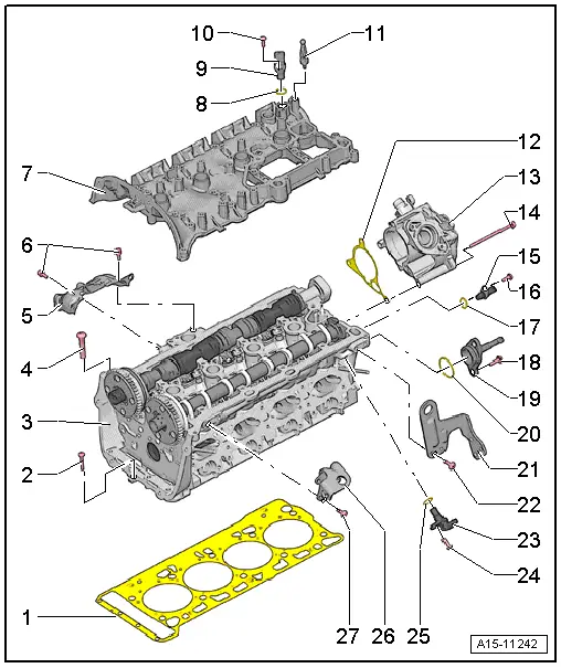
| 1 - | Cylinder head gasket |
| q | Renew |
| q | Note installation position: part number must face cylinder head |
| 2 - | Bolt |
| q | Renew |
| q | Note procedure when loosening → Fig. |
| q | Note procedure when tightening → Fig. |
| 3 - | Cylinder head |
| q | Removing and installing → Chapter |
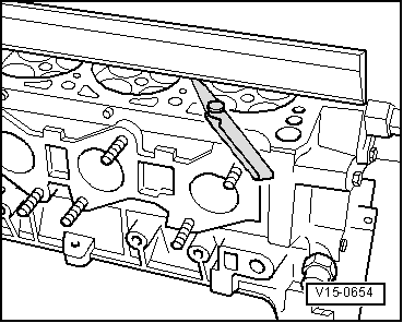
| q | Checking for distortion → Fig. |
| 4 - | Cylinder head bolt |
| q | Renew |
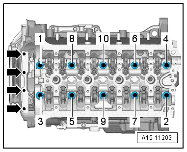
| q | Note procedure when loosening → Fig. |
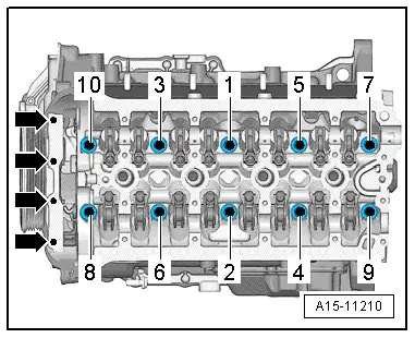
| q | Note procedure when tightening → Fig. |
| 5 - | Heat shield |
| 6 - | Bolt |
| q | 9 Nm |
| 7 - | Cylinder head cover |
| q | With integrated camshaft bearings |
| q | Clean sealing surface; machining not permitted |
| q | Remove old sealant residues |
| 8 - | O-ring |
| q | Renew |
| q | Lubricate with engine oil |
| 9 - | Hall sender 3 -G300- |
| 10 - | Bolt |
| q | 9 Nm |
| 11 - | Sealing plug |
| q | 5 Nm |
| q | With ball head for engine cover panel |
| 12 - | Gasket |
| q | Renew if damaged |
| 13 - | Vacuum pump |
| q | Removing and installing → Rep. gr.47 |
| 14 - | Bolt |
| q | Tightening torque → Rep. gr.47 |
| 15 - | Coolant temperature sender -G62- |
| 16 - | Bolt |
| q | 9 Nm |
| 17 - | O-ring |
| q | Renew |
| q | Lubricate with coolant |
| 18 - | Bolt |
| q | 9 Nm |
| 19 - | Connection |
| 20 - | O-ring |
| q | Renew |
| q | Lubricate with coolant |
| 21 - | Transport plate |
| 22 - | Bolt |
| q | 25 Nm |
| 23 - | Hall sender -G40- |
| 24 - | Bolt |
| q | 9 Nm |
| 25 - | O-ring |
| q | Renew |
| q | Lubricate with engine oil |
| 26 - | Transport plate |
| 27 - | Bolt |
| q | 25 Nm |
|
|
|
|
|
|
| 1 - | Cylinder head gasket |
| q | Renew |
| q | Note installation position: part number must face cylinder head |
| 2 - | Cylinder head bolt |
| q | Renew |
| q | Note procedure when loosening → Fig. |
| q | Note procedure when tightening → Fig. |
| 3 - | Sealing cap |
| q | With seal |
| 4 - | O-ring |
| q | Renew |
| q | Lubricate with engine oil |
| 5 - | Sealing plug |
| 6 - | Bolt |
| q | 20 Nm |
| 7 - | Bolt |
| q | 20 Nm |
| 8 - | Breather pipe |
| 9 - | Engine cover panel |
| 10 - | Bolt |
| q | Tightening sequence → Fig. |
| 11 - | Crankcase breather |
| 12 - | Gasket |
| q | Not available as replacement part |
| 13 - | Bracket |
| 14 - | Bolt |
| q | 9 Nm |
| 15 - | O-ring |
| q | Renew |
| q | Lubricate with coolant |
| 16 - | Bolt |
| q | 9 Nm |
| 17 - | Hall sender -G40- |
| 18 - | Separating plate |
| 19 - | O-ring |
| q | Renew |
| q | Lubricate with engine oil |
| 20 - | Actuator for variable valve timing |
| 21 - |
 Note
Note
|
|