audi Workshop Repair Guides

Audi Workshop Service and Repair Manuals

Cylinder head - exploded view (2.0 ltr. engine without assembly clearance feature) > < Cylinder head - exploded view (2.0 ltr. engine with assembly clearance feature)
Removing and installing cylinder head (2.0 ltr. engine with assembly clearance feature)
  Note
Camshafts with assembly clearance feature are provided with tool recesses → Fig..
Special tools and workshop equipment required
   
t  Puller -T40039-
  W00-1303
t  Assembly tool -T10352- and assembly tool -T10352/1-
  W00-10736
t  Counterhold tool -T10355-
  W00-10474
t  Locking pin -T40011-
  W00-1089
t  Assembly pin -T40196-
  W00-10735
t  Engine bung set -VAS 6122-
Removing
– 
  Note
t  Fit cable ties in the original positions when installing.
t  All open inlet and exhaust ports must be sealed with suitable plugs (e.g. from engine bung set -VAS 6122-.
–  Remove front noise insulation → Rep. gr.66.
  WARNING
Hot steam/hot coolant can escape - risk of scalding.
t  The cooling system is under pressure when the engine is hot.
t  Cover filler cap on coolant expansion tank with a cloth and open carefully to dissipate pressure.
–  Drain coolant → Chapter.
–  Remove front exhaust pipe/front silencer → Chapter.
  W00-10435
–  Remove engine cover panel -arrows-.
  A10-10719
–  Remove plenum chamber covers -1, 2 and 3-.
  A92-10115
–  Disconnect vacuum hose -3- on rear side of plenum chamber partition panel in direction of -arrow- and detach vacuum connection -2- from plenum chamber partition panel.
–  Disconnect coolant hoses on rear of cylinder head.
  A10-10878
  Caution
Protect fuel system against contamination.
Rules for cleanliness when working on the injection system → Chapter.
–  Disconnect fuel lines -1 and 2-.
–  Remove bumper cover (front) and bumper → Rep. gr.63.
–  Perform service position → Rep. gr.50.
  A20-10457
–  Unplug connector -1- from air mass meter -G70-.
–  Disconnect air intake hose -2-.
–  Pull air cleaner housing upwards -arrows-.
  A10-10997
–  Open hose clips -arrows- and detach air hose.
  A21-10302
–  Unplug the following electrical connectors:
2 - From knock sensor 1 -G61- (unplug and move clear).
3 - From intake manifold flap valve -N316-, fuel pressure sender -G247- and Hall sender -G40-
4 - From injectors
5 - From throttle valve module -J338-
6 - From intake air temperature sender -G42-
  A24-10593
–  Unplug electrical connector -2- and move wiring clear.
  A13-0361
–  Unbolt bracket for coolant pipe -arrow-.
  Note
The installation position is shown in the following illustrations with the engine removed.
  A24-10599
–  Remove intake manifold support (remove securing nut -1- and bolt -2-).
  A24-10447
–  Disconnect coolant hose -arrow-.
  A21-10141
–  Unscrew bolts -1 and 2- and move oil supply line clear to one side.
–  Unscrew bolt -3- and move coolant pipe clear to one side.
  A21-10316
–  Open hose clip -arrow-, detach air hose and swivel to side.
  A10-10995
–  Unplug electrical connectors -1 and 4- from oil pressure switch -F22- and oil pressure switch for reduced oil pressure -F378-.
  A17-10420
–  Unplug electrical connectors -1 and 2- and move wiring clear.
  A21-10314
–  Remove bolts -arrows- and detach support for turbocharger.
  A21-10315
–  Remove bolts -arrows- at oil return line.
  A21-10317
–  Unscrew nuts -arrows- and push catalytic converter to rear.
  A21-10320
–  Detach connector from camshaft control valve 1 -N205--1-.
–  Unscrew bolts -arrows- and remove camshaft control valve 1 -N205-.
  A15-10734
–  Unscrew bolts -1 to 5- and remove timing chain cover (top).
–  Remove bolts from connector rail for ignition coils.
  A15-10430
–  Release connectors -arrows- and unplug all connectors from the ignition coils at the same time.
  N28-10012
–  Remove ignition coils using puller -T40039-.
–  Remove spark plugs with spark plug spanner -3122 B-.
  A28-0074
–  Disconnect crankcase breather hose -1-.
–  Remove bolts -arrows-, detach crankcase breather system and disconnect from crankcase breather hose -2- in direction of -arrow-.
  A15-10610
–  Unplug connectors -arrows- from actuators for camshaft adjustment.
  A15-10730
–  Remove actuators for camshaft adjustment-arrows-.
  A15-10731
–  Turn sealing plugs -arrows- 90° anti-clockwise -arrow- and remove.
–  Unscrew ball heads -1 ... 2-.
–  Detach filler cap.
  A15-10556
–  Turn vibration damper to „TDC“-arrow- using counterhold tool -T10355-.
l  Notch on vibration damper must align with arrow marking on cover for timing chains (bottom).
l  The markings -1- on the camshafts must face upwards.
  A15-10451
–  Remove cylinder head bolts -1 and 2-.
  A15-10732
  Caution
Risk of irreparable damage to engine.
Only insert assembly pins -T40196- in points marked in illustration.
–  Insert assembly pins -T40196- as shown in illustration.
–  Turn crankshaft 4 rotations in direction of engine rotation.
–  Remove assembly pins -T40196-.
  A15-10738
  Caution
The timing valve has a left-hand thread.
–  Depending on version, turn assembly tool -T10352- or assembly tool -T10352/1- in direction of -arrow- to remove timing valve.
  A15-10443
–  Remove bolts -arrows- and detach bearing saddle.
  A15-10444
–  Turn vibration damper to „TDC“ position -arrow- using counterhold tool -T10355-.
l  Notch on vibration damper must align with arrow marking on cover for timing chains (bottom).
  A13-10442
–  Use a waterproof pen to mark camshaft timing chain and cylinder head -arrows- to markings on chain sprocket -1-.
  A15-11144
–  Remove sealing plug -arrow-.
  A15-10447
–  Insert scriber or suitable screwdriver in hole of chain tensioner in direction of -arrow 1- and lift locking element for chain tensioner.
–  Turn crankshaft in opposite direction to normal rotation -arrow 2- and lock in place using locking pin -T40011-.
  Note
Inlet camshaft will move in direction of engine rotation.
  A15-10560
–  Remove bolt -1- and detach tensioning rail -2- downwards.
–  Use screwdriver to release catch and press off top guide rail -3- forwards.
–  Remove camshaft timing chain from camshaft sprockets.
  Caution
Avoid damage to valves and piston crowns.
Do not turn the crankshaft after the camshaft timing chain has been removed from the cylinder head.
  A15-10602
–  Remove bolts -arrows-.
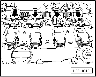
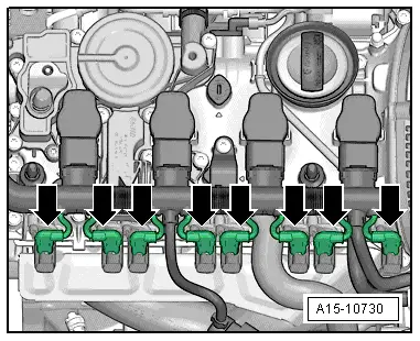
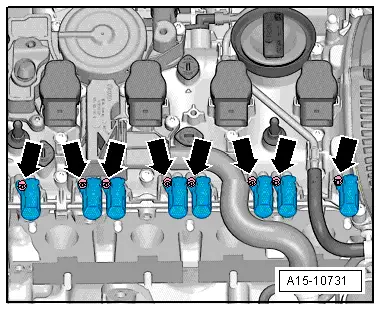
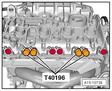
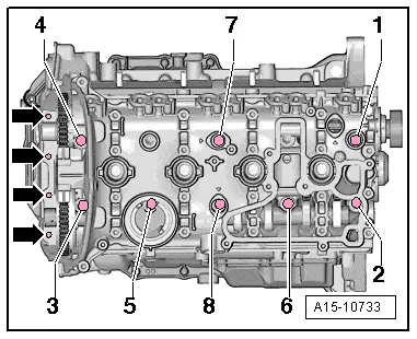
–  Remove cylinder head bolts in the sequence -1 ... 8-.
  Note
t  
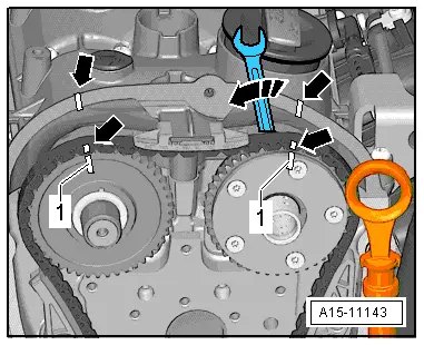
If necessary, use spanner to turn camshafts before removing cylinder head bolts.
t  
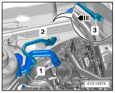
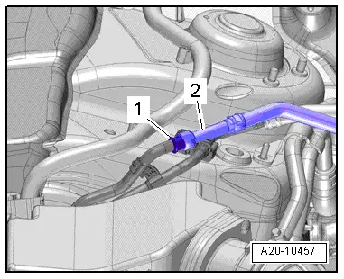
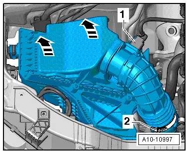
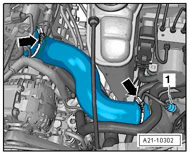
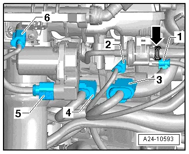
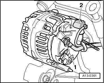
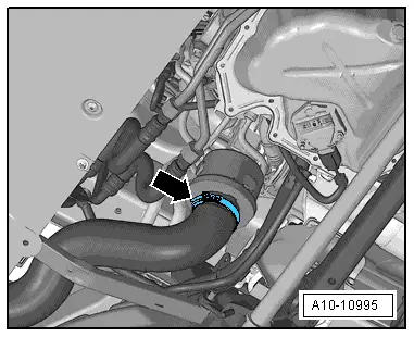
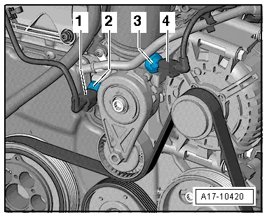
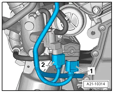
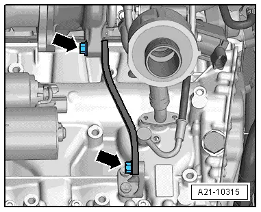
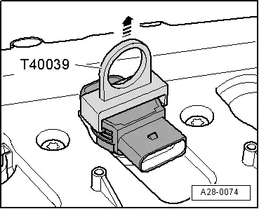
Make sure all hoses/pipes and wiring on component are removed.
t  
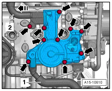
Make sure tensioning rail and guide rail are not damaged when lifting off cylinder head.
–  Take off cylinder head.
–  Place cylinder head onto soft surface (foam plastic).
Installing
l  Tightening torques → Chapter „Cylinder head - exploded view (2.0 ltr. engine with assembly clearance feature)“
  Caution
Avoid damage to sealing surfaces.
t  Carefully remove sealant residue from cylinder head and cylinder block.
t  Ensure that no long scores or scratches are made on the surfaces.
Avoid damage to cylinder block.
No oil or coolant must be allowed to remain in the blind holes for the cylinder head bolts in the cylinder block.
Ensure that cylinder head gasket seals properly:
t  Carefully remove any remaining emery and abrasive material.
t  Do not remove new cylinder head gasket from packaging until it is ready to be fitted.
t  Handle the cylinder head gasket very carefully to prevent damage to the silicone coating or the indented area of the gasket.
Avoid damage to open valves.
When installing an exchange cylinder head, the plastic protectors fitted to protect the open valves should not be removed until the cylinder head is ready to be fitted.
Avoid damage to valves and piston crowns after working on valve gear.
Turn the engine carefully at least 2 rotations to ensure that none of the valves make contact when the starter is operated.
  Note
t  Renew the bolts tightened with specified tightening angle.
t  Renew seals, gaskets and self-locking nuts.
t  Note the different sealants for sealing surfaces and cylinder head bolts.
t  Secure all hose connections with the correct type of hose clips (same as original equipment) → Electronic parts catalogue.
t  After fitting a new cylinder head or cylinder head gasket, change the engine oil and coolant.
  A15-10733
–  Place cylinder head gasket in position.
t  Note position of centring pins in cylinder block -arrows-.
t  Note installation position of cylinder head gasket. Part No. should be legible from inlet side.
  WARNING
Make sure that components are not damaged by the timing chain when rotating the crankshaft.
–  If crankshaft has been rotated: set No. 1 cylinder piston to top dead centre and then turn crankshaft back slightly.
–  Fit cylinder head.
  Note
Turn inlet camshaft using spanner to fit cylinder head bolts.
  A15-0135
–  Fit bolts -1 … 8-.
–  Tighten cylinder head bolts in the sequence -1 ... 8- in 3 stages → Item.
–  Tighten bolts -arrows- in 2 stages → Item.
  Note
Cylinder head bolts do not have to be torqued down again later after repair work.
  A15-10740
–  Turn vibration damper to „TDC“ position -arrow- using counterhold tool -T10355-.
l  Notch on vibration damper must align with arrow marking on cover for timing chains (bottom).
  Note
The camshaft timing chain links with markings must be positioned at the markings on the chain sprockets and the cylinder head.
  A13-10442
–  Use spanner to turn inlet camshaft in direction of -arrow- and fit camshaft timing chain. Markings on camshaft timing chain and cylinder head -arrows- must align with chain sprockets -1-.
  A15-11143
–  Attach bearing saddle and screw in bolts -arrows- hand-tight.
–  Remove locking pin -T40011-.
–  Tighten bolts -arrows- for bearing saddle → Chapter.
–  Install timing valve → Item.
  A15-10444
–  Insert assembly pins -T40196- as shown in illustration.
–  Turn crankshaft 4 rotations in direction of engine rotation.
–  Remove assembly pins -T40196-.
  A15-10735
–  Fit bolts -1 and 2-.
–  Tighten cylinder head bolts in the sequence -1 and 2- in 3 stages → Item.
The remaining installation steps are carried out in the reverse sequence. Note the following points:
–  Change engine oil, A4 → Booklet812, A5 → Booklet811.
–  Install timing chain cover (top) → Chapter.
–  Fill cooling system with fresh coolant → Chapter.
–  Install catalytic converter → Chapter.
–  Install front exhaust pipe/front silencer → Chapter.
  WARNING
Never use battery charging equipment for boost starting. There is danger of damaging the vehicle's control units.
  A15-10732

Cylinder head - exploded view (2.0 ltr. engine without assembly clearance feature) > < Cylinder head - exploded view (2.0 ltr. engine with assembly clearance feature)