
A4 Mk3
| Diagram of coolant hose connections |
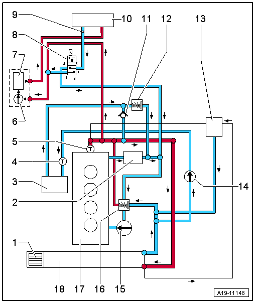
| Connection diagram for coolant hoses without 4/2-way valve (vehicles without auxiliary heater): |

| 1 - | ATF cooler |
| q | Not installed on vehicles with manual gearbox |
| 2 - | Engine oil cooler |
| q | Removing and installing → Chapter |
| 3 - | Exhaust gas recirculation cooler |
| q | Removing and installing → Chapter |
| 4 - | Radiator outlet coolant temperature sender -G83- |
| q | Removing and installing → Chapter |
| 5 - | Coolant temperature sender -G62- |
| q | Removing and installing → Chapter |
| 6 - | Coolant shut-off valve |
| q | Not fitted on all versions |
| q | Depending on production period and version of vehicle |
| q | For vehicles with auxiliary heater → Rep. gr.82 |
| 7 - | Bleeder hole |
| 8 - | Heat exchanger |
| q | If renewed, refill system with fresh coolant |
| 9 - | Coolant circulation pump -V50- |
| q | Only installed on vehicles with start/stop system |
| 10 - | Non-return valve |
| 11 - | Hose thermostat |
| 12 - | Non-return valve |
| 13 - | Coolant expansion tank |
| q | With filler cap |
| q | Checking cooling system for leaks → Chapter |
| 14 - | Pump for exhaust gas recirculation cooler -V400- |
| 15 - | Hose thermostat |
| q | Not fitted on all versions |
| q | Depending on production period and version of vehicle |
| 16 - | Coolant pump |
| q | Removing and installing → Chapter |
| 17 - | Thermostat |
| q | Removing and installing → Chapter |
| 18 - | Cylinder head/cylinder block |
| q | If renewed, refill system with fresh coolant |
| 19 - | Radiator |
| q | Removing and installing → Chapter |
| q | If renewed, refill system with fresh coolant |
| Connection diagram for coolant hoses without 4/2-way valve (vehicles with auxiliary heater): |
| 1 - | ATF cooler |
| q | Not installed on vehicles with manual gearbox |
| 2 - | Engine oil cooler |
| q | Removing and installing → Chapter |
| 3 - | Exhaust gas recirculation cooler |
| q | Removing and installing → Chapter |
| 4 - | Radiator outlet coolant temperature sender -G83- |
| q | Removing and installing → Chapter |
| 5 - | Coolant temperature sender -G62- |
| q | Removing and installing → Chapter |
| 6 - | Circulation pump -V55- |
| 7 - | Auxiliary heater |
| 8 - | Heater coolant shut-off valve -N279- |
| 9 - | Non-return valve |
| 10 - | Bleeder hole |
| 11 - | Heat exchanger |
| q | If renewed, refill system with fresh coolant |
| 12 - | Hose thermostat |
| 13 - | Non-return valve |
| 14 - | Coolant expansion tank |
| q | With filler cap |
| q | Checking cooling system for leaks → Chapter |
| 15 - | Pump for exhaust gas recirculation cooler -V400- |
| 16 - | Hose thermostat |
| q | Not fitted on all versions |
| q | Depending on production period and version of vehicle |
| 17 - | Coolant pump |
| q | Removing and installing → Chapter |
| 18 - | Thermostat |
| q | Removing and installing → Chapter |
| 19 - | Cylinder head/cylinder block |
| q | If renewed, refill system with fresh coolant |
| 20 - | Radiator |
| q | Removing and installing → Chapter |
| q | If renewed, refill system with fresh coolant |
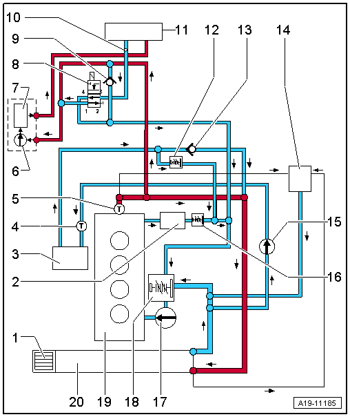
| Connection diagram for coolant hoses with 4/2-way valve with thermostat (vehicles without auxiliary heater): |

| 1 - | ATF cooler |
| q | Not installed on vehicles with manual gearbox |
| 2 - | Engine oil cooler |
| q | Removing and installing → Chapter |
| 3 - | Exhaust gas recirculation cooler |
| q | Removing and installing → Chapter |
| 4 - | Radiator outlet coolant temperature sender -G83- |
| q | Removing and installing → Chapter |
| 5 - | Coolant temperature sender -G62- |
| q | Removing and installing → Chapter |
| 6 - | Coolant shut-off valve |
| q | Not fitted on all versions |
| q | Depending on production period and version of vehicle |
| q | Activated via Climatronic coolant shut-off valve -N422- |
| 7 - | Bleeder hole |
| 8 - | Heat exchanger |
| q | If renewed, refill system with fresh coolant |
| 9 - | Coolant circulation pump -V50- |
| q | Only installed on vehicles with start/stop system |
| 10 - | Non-return valve |
| 11 - | Hose thermostat |
| 12 - | Coolant expansion tank |
| q | With filler cap |
| q | Checking cooling system for leaks → Chapter |
| 13 - | Pump for exhaust gas recirculation cooler -V400- |
| 14 - | Coolant pump |
| q | Removing and installing → Chapter |
| 15 - | 4/2-way valve with thermostat |
| q | Removing and installing → Chapter |
| q | The thermostat is located in the interior of the 4/2-way valve and cannot be renewed separately |
| 16 - | Cylinder head/cylinder block |
| q | If renewed, refill system with fresh coolant |
| 17 - | Radiator |
| q | Removing and installing → Chapter |
| q | If renewed, refill system with fresh coolant |
| Connection diagram for coolant hoses with 4/2-way valve with thermostat (vehicles with auxiliary heater): |
| 1 - | ATF cooler |
| q | Not installed on vehicles with manual gearbox |
| 2 - | Engine oil cooler |
| q | Removing and installing → Chapter |
| 3 - | Exhaust gas recirculation cooler |
| q | Removing and installing → Chapter |
| 4 - | Radiator outlet coolant temperature sender -G83- |
| q | Removing and installing → Chapter |
| 5 - | Coolant temperature sender -G62- |
| q | Removing and installing → Chapter |
| 6 - | Circulation pump -V55- |
| 7 - | Auxiliary heater |
| 8 - | Heater coolant shut-off valve -N279- |
| 9 - | Bleeder hole |
| 10 - | Heat exchanger |
| q | If renewed, refill system with fresh coolant |
| 11 - | Non-return valve |
| 12 - | Hose thermostat |
| 13 - | Coolant expansion tank |
| q | With filler cap |
| q | Checking cooling system for leaks → Chapter |
| 14 - | Pump for exhaust gas recirculation cooler -V400- |
| 15 - | Coolant pump |
| q | Removing and installing → Chapter |
| 16 - | 4/2-way valve with thermostat |
| q | Removing and installing → Chapter |
| q | The thermostat is located in the interior of the 4/2-way valve and cannot be renewed separately |
| 17 - | Cylinder head/cylinder block |
| q | If renewed, refill system with fresh coolant |
| 18 - | Radiator |
| q | Removing and installing → Chapter |
| q | If renewed, refill system with fresh coolant |