
A4 Mk3
| Removing and installing camshafts |

| t | Diesel injection pump locking pin -3359- |
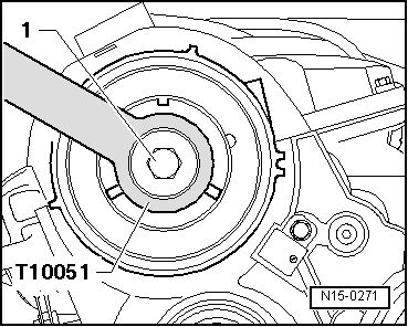
| t | Counterhold tool -T10051- |
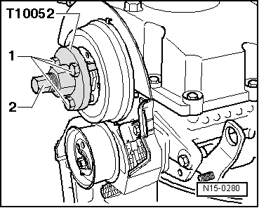
| t | Puller -T10052- |
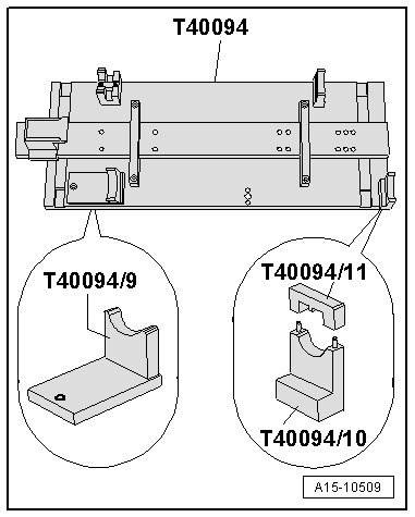
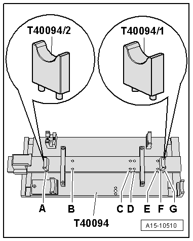
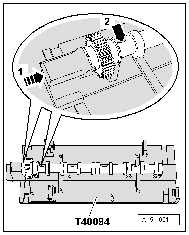
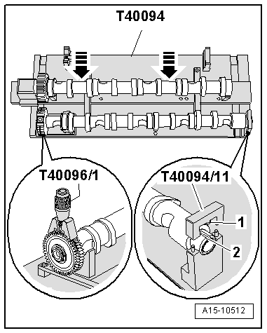
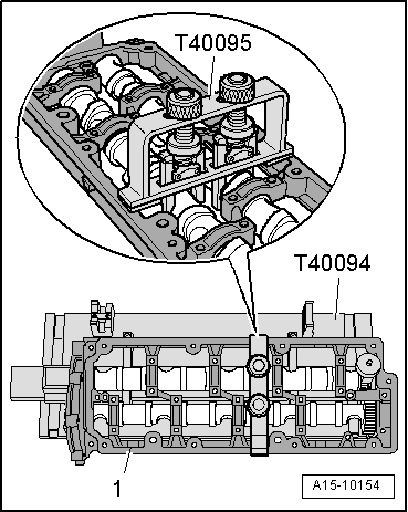
| t | Camshaft fitting tool -T40094- |
| t | Camshaft fitting tool -T40095- |
| t | Clamping tool -T40096/1- |
|
|
|
|
|
|
|
 Note
Note
|
|
|
|
Note
|
|
|
|
Note
Note
|
|
 Caution
 WARNING
|
|
|
|
|
|
|
|
|
|
Note |
|
|
|
|
|