audi Workshop Repair Guides

Audi Workshop Service and Repair Manuals

Installing engine > < Removing engine
Separating engine from manual gearbox
Special tools and workshop equipment required
t  Support set for Audi -VAS 6131/10-, supplementary set -VAS 6131/13- and gearbox support -VAS 6131/14-
   
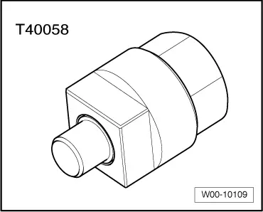
t  Adapter -T40058-
  W00-10109
Procedure
l  Engine/gearbox assembly removed and in position on scissor-type assembly platform -VAS 6131 A-.
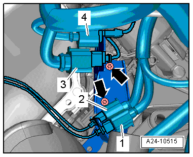
–  Remove electrical connector -1- for Lambda probe 2 after catalytic converter -G131- from bracket and unplug connector.
  Note
Disregard items marked -2, 3, 4- and -arrows-.
  A24-10515
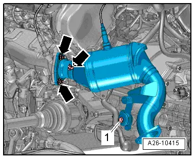
–  Remove nuts -arrows- and bolt -1- and detach catalytic converter (left-side).
  A26-10415
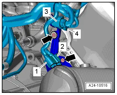
–  Remove electrical connector -1- for Lambda probe after catalytic converter -G130- from bracket and unplug connector.
  Note
Disregard items marked -2, 3, 4- and -arrows-.
  A24-10516
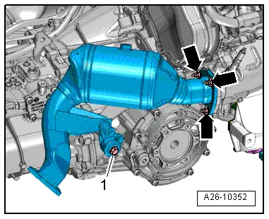
–  Remove nuts -arrows- and bolt -1- and detach catalytic converter (right-side).
  A26-10352
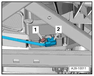
–  Unplug electrical connector -2- from engine speed sender -G28- and move wiring clear.
  Note
Disregard -item 1-.
  A28-10011
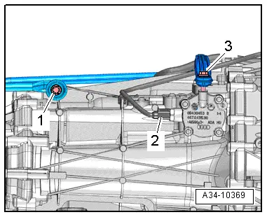
–  Unplug electrical connector -2- at reversing light switch -F4-.
  Note
Disregard -items 1, 3-.
  A34-10369
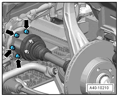
–  Unbolt drive shafts (left and right) from gearbox flange shafts.
  A40-10210
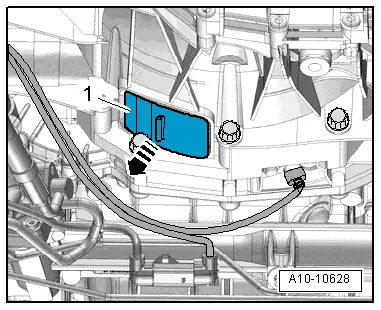
–  Detach bottom cover -1- from gearbox -arrow-.
  A10-10628
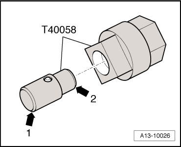
–  Insert guide pin of adapter -T40058- as follows:
l  The larger-diameter section -arrow 1- faces towards the engine.
l  The smaller-diameter section -arrow 2- faces the adapter.
  A13-10026
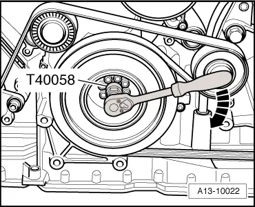
–  Counterhold crankshaft using adapter -T40058- when slackening bolts for drive plate.
  Note
When performing the next step, turn the crankshaft only in the normal direction of rotation -arrow-.
  A13-10022
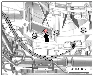
–  Remove 6 bolts -arrow- for clutch module, turning crankshaft 60° in normal direction of rotation each time.
  A10-10629
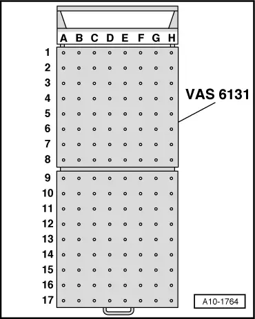
–  Set up scissor-type assembly platform -VAS 6131 A- with support set for Audi -VAS 6131/10-, supplementary set -VAS 6131/13- and gearbox support -VAS 6131/14- as follows:
  Note
The other support elements remain unchanged.
  A10-1764
Platform coordinatesParts of support set for Audi -VAS 6131/10-, supplementary set -VAS 6131/13- and gearbox support -VAS 6131/14-
F2/13-7
B10/10-1/10-2/10-5/14
G10/10-1/10-2/10-5

   
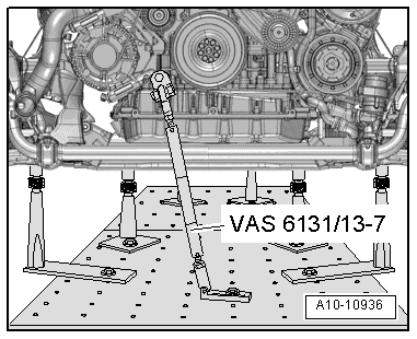
–  Secure support -VAS 6131/13-7- at tapped hole at front of engine (right-side) as illustrated.
–  Secure support -VAS 6131/13-7- to scissor-type assembly platform and tighten to 20 Nm.
  A10-10936
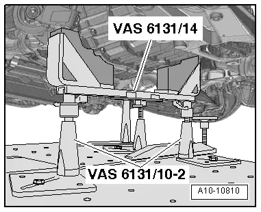
–  Position support elements from -VAS 6131/10- and gearbox support -VAS 6131/14- at front of gearbox, as illustrated.
–  Screw spindles on both sides upwards until gearbox support -VAS 6131/14- makes full contact with gearbox.
–  Tighten base plates for support elements to 20 Nm on scissor-type assembly platform -VAS 6131 A-.
  A10-10810
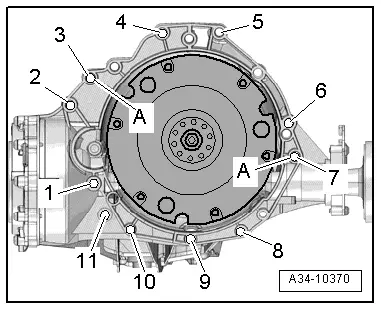
–  Remove bolts -1- and -2- for starter.
–  Separate starter from gearbox and leave in position.
–  Unscrew remaining bolts -3 ... 11- securing engine to gearbox.
  Note
Disregard -item A-.
  A34-10370
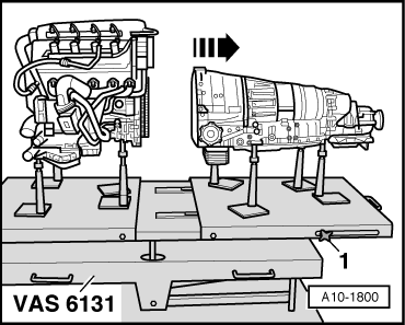
–  Loosen clamping bolts -1- on sides of scissor-type assembly platform -VAS 6131 A- and pull rear section of platform together with gearbox towards rear -arrow-.
  A10-1800

Installing engine > < Removing engine