audi Workshop Repair Guides

Audi Workshop Service and Repair Manuals

Balance shaft - exploded view > < Drive chain for auxiliary drives - exploded view
Removing and installing drive chain for auxiliary drives
Special tools and workshop equipment required
   
t  Special wrench -T40049-
  W00-10043
t  Locking pin -T40071-
t  Drill bit, Ø 8 mm
Removing
l  Gearbox removed.
–  Remove timing chain cover (bottom) → Chapter.
  W00-10238
  Caution
Make sure drive chain is not damaged.
Place a washer under the bolt heads to make sure the drive chain does not get trapped by the bolts.
–  Attach special wrench -T40049- at rear end of crankshaft using 2 old securing bolts -arrows- for drive plate.
  A13-10478
–  Unscrew plug -arrow- for “TDC” marking from cylinder block.
–  Rotate crankshaft in normal direction of rotation to “TDC”.
  Note
  A15-10525
t  The bore provided for locking the crankshaft is difficult to see when the engine is installed.
t  Therefore, turn the engine until the small notch -1- on the left-side of the vibration damper (as seen in the direction of travel) is in line with the housing joint -2- between the cylinder block and the retaining frame. This makes it easier to screw in locking pin -T40069-.
t  The marking on the vibration damper is only a visual aid. The exact “TDC” position can only be obtained by screwing in the locking pin -T40069-.
  A13-10500
–  Screw locking pin -T40069- into hole (20 Nm); if necessary, turn crankshaft backwards and forwards slightly to fully centralise locking pin.
  A13-10125
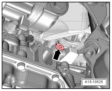
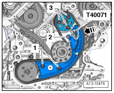
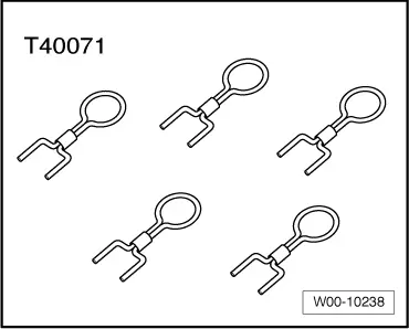
–  Press guide rail of chain tensioner in direction of -arrow- and lock chain tensioner by inserting locking pin -T40071-.
  Caution
If a used drive chain rotates in the opposite direction when it is refitted, this can cause breakage.
Mark running direction of drive chain with paint for re-installation. Do not mark drive chain by means of centre punch, notch or the like.
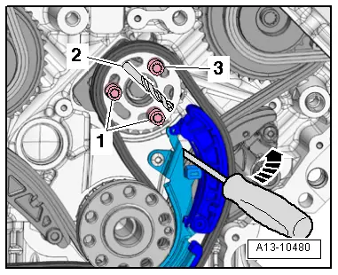
–  Unscrew bolts -3- and detach chain sprocket from balance shaft.
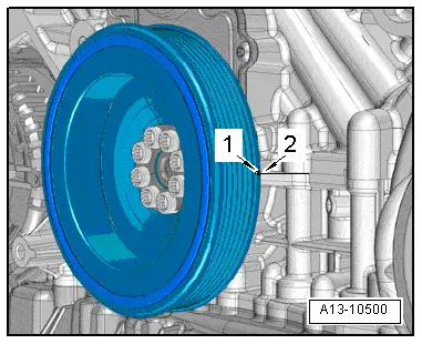
–  Remove bolts -1- and -2- and take off chain tensioner with drive chain.
  A13-10479
Installing
l  Tightening torques → Chapter, → Fig..
l  Crankshaft -1- locked in “TDC” position with locking pin -T40069-.
  A13-10125
–  Install chain tensioner with drive chain and balance shaft sprocket.
–  Wrap insulating tape around tip and shaft of 8 mm Ø drill bit to avoid cuts.
–  Lock balance shaft in “TDC” position using 8 mm Ø drill bit -item 2-.
l  The elongated holes in the balance shaft sprocket must be aligned centrally over the threaded holes in the balance shaft. If necessary move chain one tooth further.
–  Tighten bolts for chain tensioner.
–  Fit bolts -1- and -3- for chain sprocket but do not tighten.
l  It should just be possible to turn the sprocket on the balance shaft without axial movement.
–  Pull out locking pin -T40071- to release chain tensioner.
–  Press against guide rail of chain tensioner -arrow- using a screwdriver, and at the same time tighten bolts -1- and -3- securing chain sprocket.
–  Pull drill bit -2- out of balance shaft.
Remaining installation steps are carried out in reverse sequence; note the following:
–  Install timing chain cover (bottom) → Chapter.
–  Fill up with engine oil and check engine oil level → Chapter.
  A13-10480

Balance shaft - exploded view > < Drive chain for auxiliary drives - exploded view