
A4 Mk3
| Checking compression |

| Special tools and workshop equipment required |
| t | Spark plug socket and extension -3122 B- |
| t | Compression tester -V.A.G 1763- |
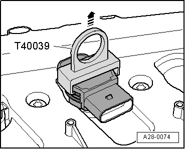
| t | Puller -T40039- |
|
|
|
|
|
|
 Note
Note
|
|
|
|
|
|
|
|
|
|
Note
|
|
Note
|
|
| Compression pressure | bar |
| When new | 10.0 … 14.0 |
| Wear limit | 9.0 |
| Maximum difference between cylinders | 3.0 |
Note
|