
A4 Mk3
| Renewing valve stem oil seals with cylinder head removed |

| Special tools and workshop equipment required |
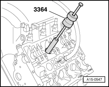
| t | Valve stem seal puller -3364- |
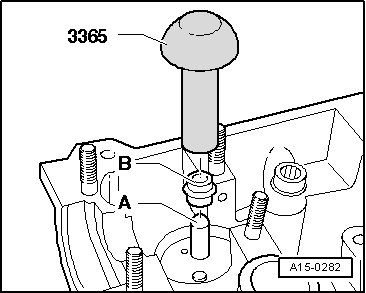
| t | Valve stem seal fitting tool -3365- |
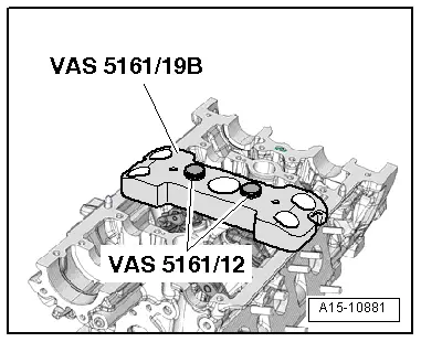
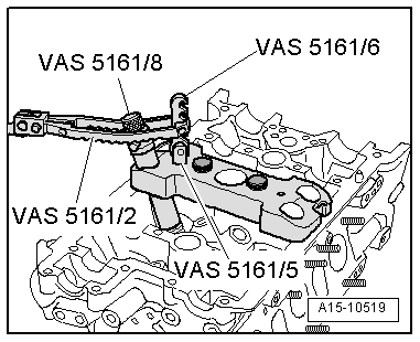
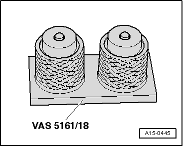
| t | Removal and installation device for valve cotters -VAS 5161 A- with guide plate for 2.0 ltr. and 3.0 ltr. FSI engine -VAS 5161/19B- |
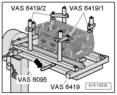
| t | Engine and gearbox support -VAS 6095- |
| t | Cylinder head tensioning device -VAS 6419- |
|
|
|
|
|
|
|
|
|
|
|
|
|
 Caution
|
|
|
|