
A4 Mk3
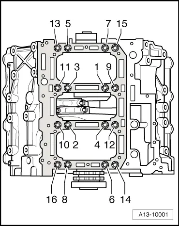
| Crankshaft - exploded view |

| 1 - | Crankshaft |
| q | Measuring axial clearance → Chapter |
| q | Measuring radial clearance → Chapter |
| q | Crankshaft dimensions → Chapter |
| 2 - | Dowel sleeve |
| q | 2x |
| q | Insert in cylinder block |
| 3 - | Retaining frame |
| 4 - | Bolt |
| q | Renew |
| q | Tightening torque and sequence → Fig. |
| 5 - | Thrust washer |
| q | Only fitted on 3rd crankshaft bearing |
| q | Installation position: oil grooves face outwards |
| q | Note location |
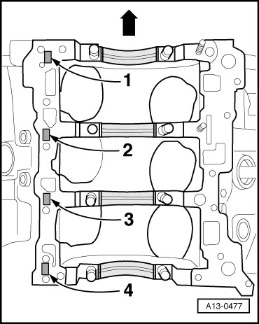
| 6 - | Bearing shell |
| q | For retaining frame |
| q | Renew used bearing shells |
| q | Install new bearing shells for retaining frame with correct coloured markings → Fig. |
| 7 - | Not fitted |
| 8 - | Dowel pin |
| q | Check that pin is firmly seated in crankshaft |
| 9 - | Thrust washer |
| q | Only fitted on 3rd crankshaft bearing |
| q | Installation position: oil grooves face outwards |
| q | Note location |
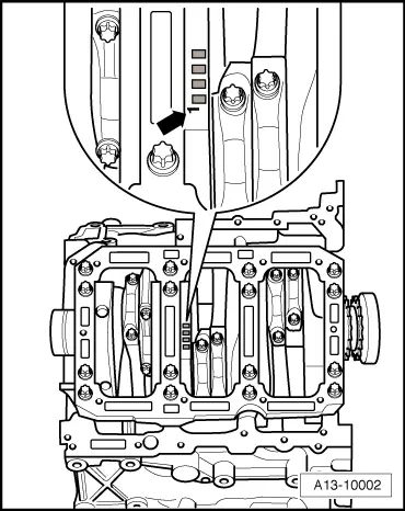
| 10 - | Bearing shell |
| q | For cylinder block (with oil groove) |
| q | Renew used bearing shells |
| q | Install new bearing shells for the cylinder block with the correct coloured markings → Fig. |
|
|
| Letter on cylinder block | Colour coding of bearing | |
| R | = | Red |
| G | = | Yellow |
| B | = | Blue |
|
|
| Letter on crankshaft | Colour coding of bearing | |
| R | = | Red |
| G | = | Yellow |
| B | = | Blue |