
A4 Mk3
| Pistons and conrods - exploded view |

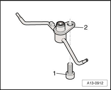
| 1 - | Bolts |
| q | Renew |
| q | Lubricate threads and contact surface |
| q | 35 Nm + turn 90° further |
| 2 - | Conrod bearing cap |
| q | Mark installation position for re-installation |
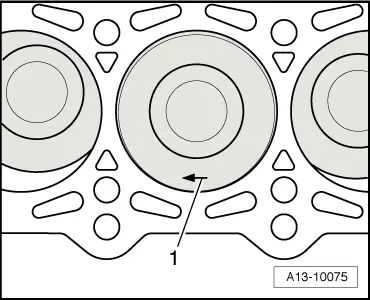
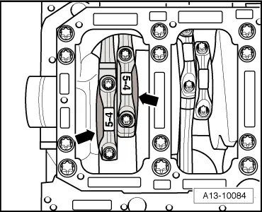
| q | Mark cylinder allocation in colour -B- → Fig. |
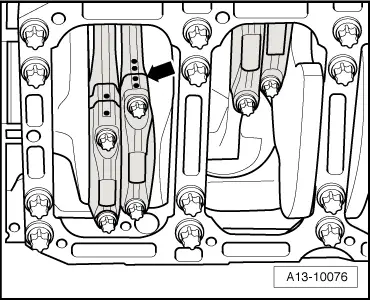
| q | Installation position: Note position of lugs on casting -A- |
| 3 - | Bearing shells |
| q | Note installation position |
| q | Renew used bearing shells |
| q | Measuring radial clearance → Chapter |
| 4 - | Conrod |
| q | Only renew as a complete set |
| q | Mark cylinder allocation in colour -B- → Fig. |
| q | Installation position: Note position of lugs on casting -A- and → Fig. |
| q | Axial clearance for each conrod pair (when new): 0.20 … 0.44 mm |
| q | Measuring radial clearance → Chapter |
| 5 - | Circlip |
| q | Renew |
| 6 - | Piston pin |
| q | If difficult to remove, heat piston to approx. 60 °C |
| q | Remove and install using drift -VW 222 A- |
| 7 - | Piston |
| q | Mark installation position and cylinder number → Fig. |
| q | Renew piston if cracking is visible on piston crown or piston skirt |
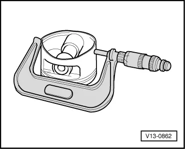
| q | Checking → Fig. |
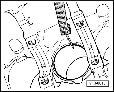
| q | Measuring cylinder bore → Fig. |
| q | Piston and cylinder dimensions → Chapter |
| q | Install using piston ring clamp |
| q | Measuring piston projection at „TDC“ → Chapter |
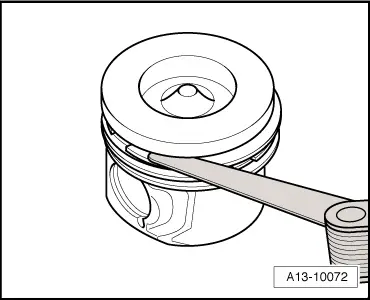
| 8 - | Piston rings |
| q | Offset gaps by 120° |
| q | Use piston ring pliers to remove and install |
| q | Inscription „TOP“ faces towards piston crown |
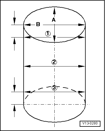
| q | Measuring ring gap → Fig. |
| q | Measuring ring-to-groove clearance → Fig. |
 Note
Note
|
|
| Piston ring | new mm | Wear limit mm |
| 1st compression ring | 0.25 … 0.38 | 0.80 |
| 2nd compression ring | 0.70 … 0.90 | 1.30 |
| Oil scraper ring | Max. 0.40 | 0.70 |
|
|
| Piston ring | new mm | Wear limit mm |
| 1st compression ring | 0.120 … 0.160 | 0.175 |
| 2nd compression ring | 0.020 … 0.090 | 0.115 |
| Oil scraper ring | 0.020… 0.090 | 0.115 |
|
|
|
|
|
|
 Caution
Note
|
|
Note
|
|