audi Workshop Repair Guides

Audi Workshop Service and Repair Manuals

Assembly mountings > < Securing engine to engine and gearbox support
Installing engine
Installing engine
Special tools and workshop equipment required
   
t  Ring spanner insert AF 16 -V.A.G 1332/14-
  W00-1329
t  Assembly aid -T40169-
  W00-10593
t  Transport lock -T40170-
Tightening torques
  Note
t  Tightening torques apply only to lightly greased, oiled, phosphated or black-finished nuts and bolts.
t  Additional lubricant such as engine oil or gearbox oil may be used, but do not use lubricant containing graphite.
t  Do not use degreased parts.
t  Tolerance for tightening torques: ± 15 %.
  W00-10594
ComponentNm
Bolts/nutsM69
M715
M820
M1040
M1265

Assembly mountings → Chapter „Assembly mountings - exploded view“.
   
Engine to manual gearbox/multitronic gearbox 0AW/dual clutch gearbox 0B5
  A34-10370
ItemBoltNm
1 1)M10x50 2)65
2 1) … 6M12x100 3)30 + 90°
7M12x125 3)30 + 90°
8, 11M10x60 3)15 + 90°
9, 10M10x95 3)15 + 90°
ADowel sleeves for centralising
l  1) Also secures starter
l  2) Property class 10.9. The steel bolt may be re-used as often as necessary.
l  3) Aluminium bolts must not be used more often than twice → Anchor.

   
The aluminium bolts -2 … 11- must not be used more often than twice. After the first use, the bolts must therefore be identified with an „X“ made by two chisel marks -arrow-.
To avoid damaging the bolts when making this mark, do not clamp them directly in a vice. Clamp a 14 mm socket with 1/2" drive in a vice and insert the bolt as shown.
Bolts already marked with an „X“ must not be used again.
Procedure
  Note
t  Renew the bolts tightened with specified tightening angle.
t  Renew self-locking nuts and bolts as well as seals, gaskets and O-rings.
t  Do not remove plugs or protective caps until you are ready to fit the relevant line.
t  Secure all hose connections with the correct type of hose clips (same as original equipment) → Electronic parts catalogue.
t  Fit all cable ties in the original positions when installing.
–  Before installing gearbox, remove residue from threaded holes for engine/gearbox bolts in cylinder block using a thread tap.
  A10-11113
–  The following preparations are required before joining engine and gearbox.
–  Insert assembly aid -T40169- into gearbox housing and clutch module/dual-mass flywheel from below, as illustrated.
l  The assembly aid -T40169- must engage in the semi-circular recess -1- and in the inspection hole -2-.
  Note
There is only one inspection hole on the circumference; turn the clutch module/dual-mass flywheel accordingly.
–  Insert pin of assembly aid into hole on gearbox housing.
  A10-10825
–  Insert transport lock -T40170- into gearbox housing from below and clamp onto flange shaft -1-.
  A10-10826
–  Check whether dowel sleeves -A- for centring engine and gearbox are fitted in cylinder block; install missing dowel sleeves.
–  Check whether aluminium bolts securing engine to gearbox can be reused; if so, apply marking → Anchor.
–  Bring gearbox into position on engine and tighten bolts -1 … 11-.
–  Remove transport lock -T40170- and assembly aid -T40169-.
  Note
  A34-10370
The following step is necessary to ensure that the clutch module/dual-mass flywheel is straight and that it makes even contact with the drive plate.
–  Use assembly lever -1- to press clutch module/dual-mass flywheel -2- slightly against drive plate -3- in direction of -arrow-.
  A34-10497
–  Bolt clutch module/dual-mass flywheel onto drive plate as follows:
  Note
Use ring spanner insert AF 16 -V.A.G 1332/14- to tighten bolts.
–  Hand-tighten first bolt -arrow- (2 Nm).
  A10-10629
–  Insert guide pin of adapter -T40058- as follows:
l  The larger-diameter section -arrow 1- faces towards the engine.
l  The smaller-diameter section -arrow 2- faces the adapter.
  A13-10026
–  Turn crankshaft 180° further in normal direction of engine rotation -arrow- with adapter -T40058-.
  A13-10022
–  Tighten bolt accessible in this crankshaft position -arrow- to specified torque → Rep. gr.34 or → Rep. gr.37.
–  Turn crankshaft by 60° each time and tighten remaining 5 bolts to specified torque → Rep. gr.34 or → Rep. gr.37.
–  Hold ATF lines in installation position when joining engine and subframe.
–  Install engine support and engine mounting → Chapter.
–  Bolt drive shafts (left and right) onto gearbox flange shafts → Rep. gr.40.
–  Vehicles with multitronic gearbox 0AW: Install ATF lines → Rep. gr.34.
–  Vehicles with dual clutch gearbox 0B5: Install ATF-lines → Rep. gr.37.
–  Install particulate filter:
t  Vehicles with manual gearbox/multitronic gearbox 0AW → Chapter
t  Vehicles with dual clutch gearbox 0B5 → Chapter.
  A10-10629
Vehicles with manual gearbox or dual clutch gearbox 0B5:
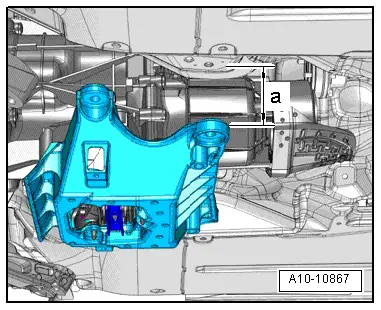
–  Raise engine/gearbox assembly using scissor-type assembly platform -VAS 6131 A- only until distance between tunnel cross member and body is -a-.
l  Dimension -a- = min. 100 mm.
–  Vehicles with manual gearbox: Install selector rod and push rod → Rep. gr.34.
–  Vehicles with dual clutch gearbox 0B5: Install selector lever cable → Rep. gr.34.
All vehicles (continued):
–  Raise engine/gearbox assembly using scissor-type assembly platform -VAS 6131 A-.
–  Align subframe and tunnel cross member on longitudinal members according to markings made before removal.
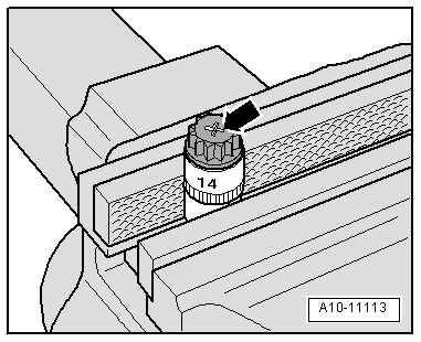
–  Tighten subframe bolts only to specified torque (do not turn further); the bolts are only to be fully tightened after performing the wheel alignment check → Rep. gr.40.
  WARNING
Risk of accident because of loose bolt connections.
Do NOT drive the vehicle unless the subframe bolts have been finally tightened.
–  Tighten bolts for tunnel cross member → Rep. gr.34 or → Rep. gr.37.
Remaining installation steps are carried out in reverse sequence; note the following:
–  Vehicles with four-wheel drive: Install propshaft → Rear final drive 0BC; Rep. gr.39 or → Rear final drive 0BF and 0BE - sport differential; Rep. gr.39.
–  Vehicles with manual gearbox: Install slave cylinder → Rep. gr.30.
–  Install front cross member → Rep. gr.66.
–  Vehicles with multitronic gearbox 0AW: Install selector lever cable → Rep. gr.37.
–  Secure intermediate steering shaft on steering box → Rep. gr.48.
–  Install subframe cross brace, upper suspension links, anti-roll bar and, where appropriate, diagonal struts; secure suspension strut to track control link → Rep. gr.40.
–  Install brake calipers → Rep. gr.46.
–  Install engine control unit → Rep. gr.23.
–  Install filler neck for washer fluid reservoir → Electrical system; Rep. gr.92.
–  Electrical connections and routing → Current flow diagrams, Electrical fault finding and Fitting locations.
–  Install electrical wiring, terminal 30 wiring junction 2 -TV22- and cover for electronics box in engine compartment → Electrical system; Rep. gr.97.
–  Install refrigerant lines → Rep. gr.87.
–  Observe notes on procedure for connecting the battery → Electrical system; Rep. gr.27.
  Caution
Risk of irreparable damage to control units because of excessive voltage.
Never use battery charging equipment for boost starting.
–  Install air cleaner housing → Rep. gr.23.
–  Install lock carrier cover → Rep. gr.63.
–  Install plenum chamber cover and strut for lock carrier → Rep. gr.50.
–  Fill up with engine oil and check oil level → Booklet811, → Booklet812 or → Booklet818.
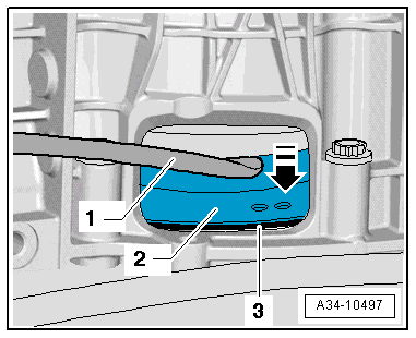
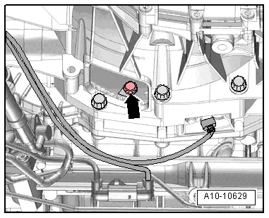
–  Connect coolant hoses with plug-in connector → Fig..
–  Fill up with coolant → Anchor.
  Note
t  Drained-off coolant may only be used again if the original cylinder head and cylinder block are re-installed.
t  Contaminated or dirty coolant must not be used again.
–  Bleed fuel system → Rep. gr.23.
–  Charge refrigerant system → Air conditioner with refrigerant R134a.
–  Install wheel housing liners → Rep. gr.66.
–  Fit front wheels → Wheels and tyres; Rep. gr.44.
–  Perform wheel alignment check → Rep. gr.44.
  WARNING
Risk of accident because of loose bolt connections.
Tighten subframe bolts to final setting after performing wheel alignment check.
–  Fill up with ATF → Rep. gr.34 or → Rep. gr.37.
–  Install noise insulation panels → Rep. gr.66.
  A10-10867

Assembly mountings > < Securing engine to engine and gearbox support