| –
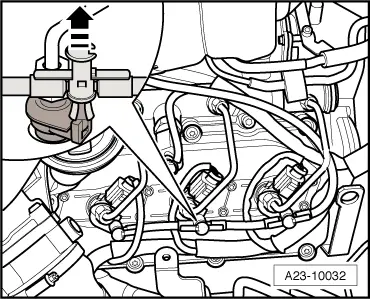
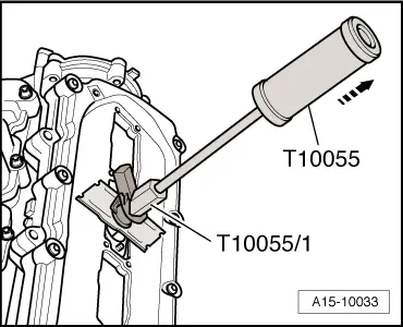
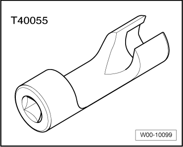
| Pull out injectors using puller -T10055- with adapter -T10055/1-. |
| –
| After removal, lay injectors on a clean cloth. |
| When installing new injectors, the following components must be renewed: |
| t
| Renew O-ring for injector bore. |
| t
| O-ring for fuel return line connection |

Note | t
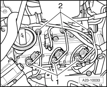
| Note identification marks for cylinder allocation when re-installing high-pressure pipes. |
| t
| The high-pressure pipes can be re-used after performing the following checks: |
| t
| Check taper seats of high-pressure pipes for deformation and cracks. |
| t
| The bore of the pipe must not be distorted, restricted or otherwise damaged. |
| t
| Corroded pipes must not be used again. |
| Installing used injectors |
| When re-installing used injectors, the following components must be renewed: |
| t
| Renew O-ring for injector bore. |
| t
| O-ring for fuel return line connection |
| –
| Spray tip of injector nozzle with rust-releasing spray. Wait approx. 5 minutes and wipe off soot particles and oil with a cloth. |
| –
| If an injector is very dirty, the tip of the nozzle should also be cleaned with a soft brass wire brush to make it easier to remove the copper seal. Do not apply the wire brush to the bores in the nozzle. |
| –
| To remove the old copper seal from the injector, clamp the seal carefully in a vice so that it is just held between the jaws without turning. Then carefully pull and twist the injector out of the copper seal by hand. |
| –
| Clean off deposits under the copper seal using a suitable scraper. |
| –
| Use a plastic bush to fit the new copper seal. |
Note | Lubricate all O-rings with engine oil or assembly oil before installing. |

Caution | Risk of damage to injector sealing surface. |
| To remove carbon deposits from the injector sealing surface, clean the injector bore in the cylinder head with a cloth soaked in engine oil or rust solvent. |
|
| –
| Hand-tighten union nuts on high-pressure pipes. Make sure that connections are not under tension. |
| –
| Press return line connections carefully over seals and onto injectors (check seal for damage before connecting return line). The catch should engage audibly. Then press release pin down carefully. |
| After renewing one or more injectors, the „injector delivery calibration values“ and „injector voltage calibration values“ for the new injectors must be written into the engine control unit → Chapter. |
| Additionally, check that the „injector delivery calibration values“ and „injector voltage calibration values“ are correctly entered for all the other injectors. Do NOT attempt to re-enter these calibration values if the correct values are already stored in the engine control unit. |
| Bleeding fuel system and checking for leaks |
Note | The fuel system is self-bleeding; do not open the high-pressure connections. |
| –
| Run engine at idling speed for several minutes and then switch off. |
| –
| Check the complete fuel system including all 6 return line connections for leaks. |
| Renew affected component if leakage still occurs after tightening to correct torque. |
Note | The return lines can only be renewed together with the pressure retention valve as one unit. |
| –
| After completing the repair, road-test the vehicle. Accelerate with full throttle at least once. Then inspect high-pressure section of fuel system again for leaks. |
Note | If there is any air left in the fuel system, the engine may switch to the backup mode ('emergency running' mode) during the road test. Switch off the engine and erase the event memory. Then continue the road test. |
| l
| Tightening torques: refer to exploded view of fuel system → Chapter. |
|
|
|

 WARNING