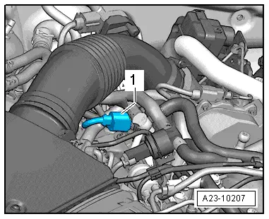
| The fuel pressure regulating valve -N276--1- is located in the right-side fuel rail (cylinder bank 1). It maintains a constant pressure in the rail and the injector pipes (high-pressure fuel circuit). |
| If the pressure in the high-pressure fuel circuit is too high, the regulating valve opens to allow some of the fuel to flow back from the fuel rail to the fuel tank via a return line. |
| If the pressure in the high-pressure fuel circuit is too low, the valve closes and seals off the high-pressure section of the system from the low-pressure section. |
| The fuel pressure regulating valve -N276- cannot be re-used. |

WARNING | t
| Always read rules for cleanliness and instructions for working on fuel system → Chapter. |
| t
| Follow these instructions and rules for cleanliness before starting work and while working on the fuel system. |
|
| –
| Remove intake hose between air mass meter -G70- and turbocharger. |
| –
| Before removal, clean area around thread for fuel pressure regulating valve using cleaning solution or similar (no dirt must enter opening in fuel rail). |

Note | Clean carefully; cleaning solution must not enter the electrical connector. |
| –
| Dry off fuel pressure regulating valve -N276-. |
| –
| Remove banjo bolt for fuel return lines (make sure that all parts are clean). |
| –
| Open cable tie securing wiring harness located above fuel pressure regulating valve -N276-. |
| –
| Detach electrical connector at fuel pressure regulating valve -N276-. |
| –
| Slacken union nut (counterhold at hexagon flats on housing). Then unscrew and remove by hand. |
| –
| Extract dirt from opening in fuel rail (thread and sealing surface) using a vacuum cleaner. Do not use metal tools, etc. |
Note | Seal off opening in fuel rail immediately with a suitable plug to prevent dirt from entering. |
Note | t
| The fuel pressure regulating valve -N276- has a deformable sealing lip and no separate seal; it can therefore be used only once. |
| t
| Check that sealing surfaces (deformable sealing lip) and threads on new fuel pressure regulating valve -N276- are not damaged. |
| t
| Check sealing surface at opening in fuel rail. |
| t
| The beginning of the thread and the deformable sealing lip of the fuel pressure regulating valve -N276- must be coated with diesel fuel. |
| –
| Screw on union nut by hand. |
| –
| Align regulating valve so that connecting wire is free of tension after connector is attached. |
| –
| Use suitable torque wrench with an open-end spanner insert (30 mm) to tighten union nut. |
| Tightening torque: Tighten union nut in 2 stages. |
| Stage 1: 60 +/-5 Nm (counterhold hexagon flats on housing). |
| Then back off union nut 90° (1/4 turn; counterhold hexagon flats on housing). |
| Stage 2: 95 +5 Nm (counterhold hexagon flats on housing). |
| –
| Tighten banjo bolt for fuel return lines with new seals to 25 Nm. |
| –
| Remove intake hose between air mass meter -G70- and turbocharger. |
| –
| The remaining installation steps are carried out in the reverse sequence. |
| –
| After installation, run engine at moderate speed for several minutes and then switch off. |
| –
| Check fuel system for leaks. |
| –
| Interrogate event memory. |
| After renewing high-pressure pump and/or fuel pressure regulating valve -N276-, adaption must be performed. |
| –
| After completing the repair, road-test the vehicle. Accelerate with full throttle at least once. Then check the high-pressure section of the fuel system again for leaks. |
| –
| Interrogate event memory again. |
|
|
|
