
A4 Mk3
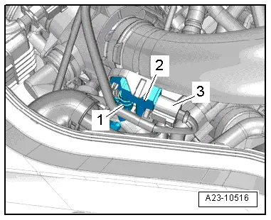
| Overview of fitting locations |
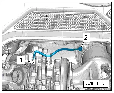
| Engine compartment |

| 1 - | Air mass meter -G70- |
| q | Removing and installing → Chapter |
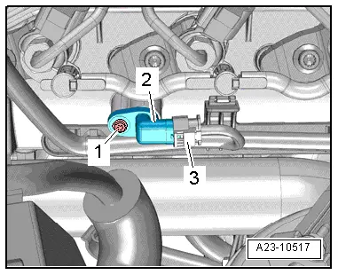
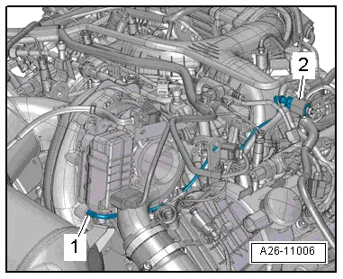
| 2 - | Electrical connector for exhaust gas recirculation temperature sensor -G98- |
| q | Removing and installing → Rep. gr.26 |
| 3 - | Electrical connector |
| q | For map-controlled engine cooling system thermostat -F265-, fuel metering valve -N290- and exhaust gas recirculation control motor -V338- |
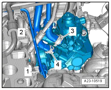
| 4 - | Restrictor |
| q | In fuel return line |
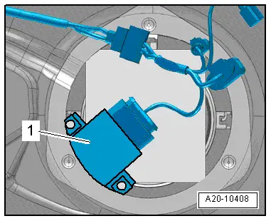
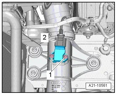
| 5 - | Pressure differential sender -G505- |
| q | Fitting location → Fig. |
| q | Exploded view → Chapter |
| q | Removing and installing → Chapter |
| 6 - | Fuel temperature sender -G81- |
| 7 - | Electrical connector for exhaust gas temperature sender 3 -G495- |
| q | Fitting location → Fig. |
| q | Exploded view → Chapter |
| 8 - | Control unit for turbocharger 1 -J724- |
| q | On turbocharger (left-side) |
| q | Removing and installing → Rep. gr.21 |
| 9 - | Exhaust gas temperature sender 1 -G235- |
| q | Fitting location → Fig. |
| q | Removing and installing → Rep. gr.26 |
| 10 - | Jump start box |
| 11 - | Exhaust gas temperature sender 3 -G495- |
| q | Removing and installing → Rep. gr.26 |
| 12 - | Coolant valve for cylinder head -N489- |
| 13 - | Lambda probe -G39- with Lambda probe heater -Z19- |
| q | Exploded view → Chapter |
| q | Removing and installing → Chapter |
| 14 - | Exhaust gas recirculation control motor -V338- |
| q | Removing and installing → Rep. gr.26 |
| 15 - | Coolant temperature sender -G62- |
| 16 - | Electrical connector for Lambda probe -G39- |
| q | Exploded view → Chapter |
| 17 - | Engine control unit -J623- |
| q | Fitting location → Fig. |
| q | Removing and installing → Chapter |
| 18 - | Charge pressure sender -G31-/intake air temperature sender -G42- |
| q | Fitting location → Fig. |
| q | Removing and installing → Rep. gr.21 |
| q | 5 Nm |
| 19 - | Throttle valve module -J338- |
| q | Exploded view → Chapter |
| 20 - | Injectors |
| q | Cylinder bank 2 |
| q | Removing and installing → Chapter |
| 21 - | Fuel pressure sender -G247- |
| q | Removing and installing → Chapter |
| 22 - | Valve for oil pressure control -N428- |
| q | Removing and installing → Rep. gr.17 |
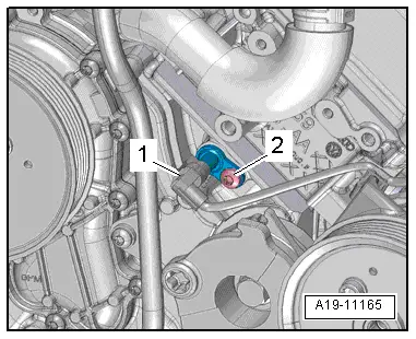
| 23 - | Temperature sender for engine temperature regulation -G694- |
| q | Fitting location → Fig. |
| 24 - | Intake manifold flap motor -V157- |
| q | Exploded view → Chapter |
| 25 - | Exhaust gas recirculation cooler change-over valve -N345- |
| q | Removing and installing → Rep. gr.26 |
| 26 - | Oil pressure switch for reduced oil pressure -F378- |
| q | Removing and installing → Rep. gr.17 |
| 27 - | Oil pressure switch -F22- |
| q | Removing and installing → Rep. gr.17 |
| 28 - | Fuel pressure regulating valve -N276- |
| q | Exploded view → Chapter |
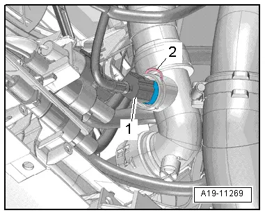
| 29 - | Radiator outlet coolant temperature sender -G83- |
| q | Fitting location → Fig. |
| 30 - | Injectors |
| q | Cylinder bank 1 |
| q | Removing and installing → Chapter |
| Engine (top view) |

| 1 - | Fuel pressure regulating valve -N276- |
| q | Exploded view → Chapter |
| 2 - | Injector, cylinder 1 -N30- |
| q | Exploded view → Chapter |
| 3 - | Glow plug 1 -Q10- |
| q | Exploded view → Chapter |
| 4 - | Injector, cylinder 2 -N31- |
| q | Exploded view → Chapter |
| 5 - | Hall sender -G40- |
| q | Fitting location → Fig. |
| q | Exploded view → Chapter |
| 6 - | Glow plug 2 -Q11- |
| q | Exploded view → Chapter |
| 7 - | Injector, cylinder 3 -N32- |
| q | Exploded view → Chapter |
| 8 - | Glow plug 3 -Q12- |
| q | Exploded view → Chapter |
| 9 - | Fuel temperature sender -G81- |
| 10 - | Control unit for turbocharger 1 -J724- |
| q | On turbocharger |
| q | Removing and installing → Rep. gr.21 |
| 11 - | Fuel metering valve -N290- |
| q | Fitting location → Fig. |
| 12 - | Exhaust gas recirculation control motor -V338- |
| q | Removing and installing → Rep. gr.26 |
| 13 - | Fuel pressure sender -G247- |
| q | Removing and installing → Chapter |
| 14 - | Glow plug 6 -Q15- |
| q | Exploded view → Chapter |
| 15 - | Injector, cylinder 6 -N84- |
| q | Exploded view → Chapter |
| 16 - | Glow plug 5 -Q14- |
| q | Exploded view → Chapter |
| 17 - | Injector, cylinder 5 -N83- |
| q | Exploded view → Chapter |
| 18 - | Glow plug 4 -Q13- |
| q | Exploded view → Chapter |
| 19 - | Injector, cylinder 4 -N33- |
| q | Exploded view → Chapter |
| 20 - | Coolant temperature sender -G62- |
| 21 - | Coolant valve for cylinder head -N489- |
| Engine (front view) |
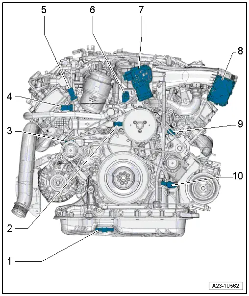
| 1 - | Oil level and oil temperature sender -G266- |
| q | Removing and installing → Rep. gr.17 |
| 2 - | Map-controlled engine cooling system thermostat -F265- |
| q | Removing and installing → Rep. gr.19 |
| 3 - | Oil temperature sender 2 -G664- |
| q | Removing and installing → Rep. gr.17 |
| 4 - | Oil pressure switch -F22- |
| q | Removing and installing → Rep. gr.17 |
| 5 - | Oil pressure switch for reduced oil pressure -F378- |
| q | Removing and installing → Rep. gr.17 |
| 6 - | Exhaust gas recirculation cooler change-over valve -N345- |
| q | Removing and installing → Rep. gr.26 |
| 7 - | Intake manifold flap motor -V157- |
| q | Exploded view → Chapter |
| 8 - | Throttle valve module -J338- |
| q | Exploded view → Chapter |
| 9 - | Temperature sender for engine temperature regulation -G694- |
| q | Fitting location → Fig. |
| 10 - | Valve for oil pressure control -N428- |
| q | Removing and installing → Rep. gr.17 |
|
|
 Note
Note
|
|
|
|
|
|
|
|
|
|
|
|
|
|
|
|
|
|
|
|
|
|