audi Workshop Repair Guides

Audi Workshop Service and Repair Manuals

Removing and installing upper links > < Servicing suspension strut and mounting bracket
Removing and installing shock absorber fork
Special tools and workshop equipment required
   
t  Spreader -3424-
  W00-0413
t  Torque wrench -V.A.G 1331-
  W00-0427
t  Torque wrench -V.A.G 1332-
  W00-0428
t  Ball joint puller -T40010 A-
Removing
–  Remove wheel.
  W00-10591
–  Unscrew nuts -1- and detach cover -2-.
–  Remove noise insulation → Rep. gr.66.
  A40-10212
–  On vehicles with vehicle level sender, unscrew nut -2-.
–  Detach bolt connection -2-.
  A40-10217
–  Detach bolt connections -1- and -3-.
–  Take out coupling rod -2-.
  A40-10261
–  Unscrew nut -1- on joint pin -2- of track rod ball joint until it is flush with end of thread. Counterhold if necessary when loosening.
Leave nut screwed on a few turns to protect threads on joint pin.
  A48-10398
–  Press track rod ball joint off wheel bearing housing using ball joint puller -T40010 A-. Then remove nut.
  A40-10222
–  Detach bolt connection -3-.
–  Detach bolt connection -1-, guide out track control link and swivel forwards.
  Note
To remove bolt -1-, turn steering box fully to left or right depending on which side of the vehicle you are working on.
  A40-10217
–  Detach bolt connection -1-.
  A40-10223
–  Insert spreader -3424- in slot in wheel bearing housing.
–  Turn ratchet handle through 90° and pull ratchet handle off spreader -3424-.
–  Pull shock absorber fork -1- downwards off shock absorber tube and remove.
Installing
Installation is carried out in the reverse sequence. Note the following points:
Tightening torques → Chapter „Exploded view of suspension strut with mounting bracket, shock absorber fork, upper links, body brace“
Tightening torques → Chapter „Removing and installing track control link“
  Note
  A40-10258
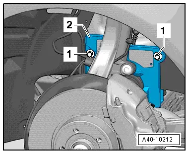
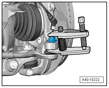
When fitting, ensure T-bolt -arrow- engages in groove of shock absorber fork.
  Note
Bonded rubber bushes can only be turned to a limited extent. The suspension mountings must therefore only be tightened when the suspension is in the unladen position or reference position.
–  Lifting suspension to unladen position → Chapter „Lifting suspension to unladen position (vehicles with coil springs)“
–  On vehicles with automatic headlight range control, carry out basic adjustment of headlights → Rep. gr.94.
–  If, on vehicles with electronic damping control, the vehicle level sender has been removed and refitted or the linkage detached, the reference position must be re-adapted → Chapter. → Vehicle diagnostic, testing and information system VAS 5051
–  If the reference position has been re-adapted on vehicles with lane departure warning, the lane departure warning control unit -J759- must be recalibrated → Chapter.
–  Secure wheel → Wheels and tyres; Rep. gr.44.
–  Wheel alignment must be checked and adjusted, see chart → Chapter.
  A40-10258

Removing and installing upper links > < Servicing suspension strut and mounting bracket