audi Workshop Repair Guides

Audi Workshop Service and Repair Manuals

Renewing bush for track control link > < Exploded view of track control link, swivel joint, guide link, vehicle level sender
Removing and installing track control link
Special tools and workshop equipment required
   
t  Engine and gearbox jack -V.A.G 1383 A-
  W00-0120
t  Ball joint puller -T40010 A-
  W00-10591
t  Ring spanner insert -V.A.G 1332/10-
  W00-0953
t  or ring spanner insert -V.A.G 1332/7-
Removing
–  Remove wheel.
–  Remove noise insulation → Rep. gr.66.
  W00-10096
–  On vehicles with vehicle level sender, unscrew nut -2-.
–  Detach bolt connection -3-.
  A40-10217
–  Unscrew nut -1- on joint pin -2- of track rod ball joint until it is flush with end of thread. Counterhold if necessary when loosening.
Leave nut screwed on a few turns to protect threads on joint pin.
  A48-10398
–  Press track rod ball joint off wheel bearing housing using ball joint puller -T40010 A-. Then remove nut.
  Note
Make sure the two lever arms of the puller are parallel when maximum force is exerted; adjust as necessary.
  A40-10222
–  Detach bolt connection -1-.
  Note
To remove bolt -1-, turn steering box fully to left or right depending on which side of the vehicle you are working on.
–  Guide out track control link and swivel towards rear.
–  Unscrew nut on swivel joint pin until it is flush with end of thread. Counterhold if necessary when loosening.
  A40-10217
–  Press swivel joint pin out of tapered seat using ball joint puller -T40010 A-.
  Note
t  Make sure the two lever arms of the puller are parallel when maximum force is exerted; adjust as necessary.
t  Take care not to damage drive shaft boot.
t  To avoid damage to joints of upper links, support wheel bearing housing (e.g. using engine and gearbox jack -V.A.G 1383 A-) to prevent the suspension from extending too far.
–  Remove nut from joint pin of track control link.
–  Take out track control link.
Installing
Installation is carried out in the reverse sequence. Note the following points:
Tightening torques → Chapter „Exploded view of track control link, swivel joint, guide link, vehicle level sender“
  Note
t  Bonded rubber bushes can only be turned to a limited extent. The suspension mountings must therefore only be tightened when the suspension is in the unladen position or reference position.
t  Lifting suspension to unladen position → Chapter „Lifting suspension to unladen position (vehicles with coil springs)“
  A40-10220
t  
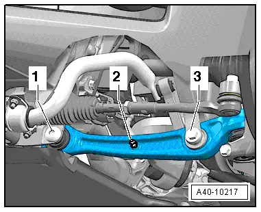
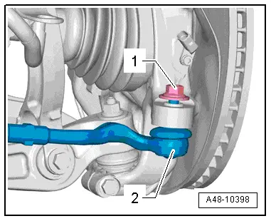
When tightening bolt connection -1-, track control link must be pressed towards inside of vehicle.
–  Remove remaining adhesive from thread of joint pin on swivel joint.
–  On vehicles with automatic headlight range control, carry out basic adjustment of headlights → Rep. gr.94.
–  If, on vehicles with electronic damping control, the vehicle level sender has been removed and refitted or the linkage detached, the reference position must be re-adapted → Chapter. → Vehicle diagnostic, testing and information system VAS 5051
–  If the reference position has been re-adapted on vehicles with lane departure warning, the lane departure warning control unit -J759- must be recalibrated → Chapter.
–  Secure wheel → Wheels and tyres; Rep. gr.44.
–  Wheel alignment must be checked and adjusted, see chart → Chapter.
  A40-10217

Renewing bush for track control link > < Exploded view of track control link, swivel joint, guide link, vehicle level sender