audi Workshop Repair Guides

Audi Workshop Service and Repair Manuals

Lane departure warning (Audi lane assist) > < Adjustment procedure using ACC setting deviceVAS 6190
Adjustment procedure using ACC setting deviceVAS 6430
Adjustment procedure using ACC setting device -VAS 6430-
Special tools and workshop equipment required
   
t  Vehicle diagnostic, testing and information system -VAS 5051 B- with appropriate diagnosis cable
  W00-10343
t  ACC setting device -VAS 6430-
t  Wheel alignment computer
  W00-10590
t  
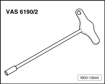
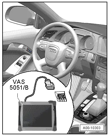
Adjusting tool -VAS 6190/2-
  Note
t  
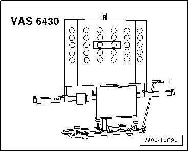
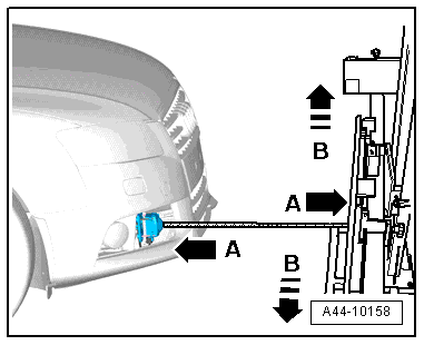
Before driving the vehicle onto the alignment platform, make sure there is sufficient space between the vehicle and the ACC setting device-VAS 6430-. The distance between the ACC setting device-VAS 6430- and the vehicle must be 120 cm ± 5 cm.
t  If the available space is not adequate, drive the vehicle backwards onto the alignment platform as required.
t  
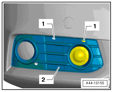
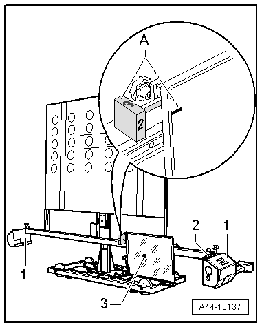
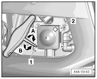
Before commencing the adjustment procedure, check in which position the adjustment mirror is located. If necessary, the adjustment mirror must be repositioned before performing the adjustment.
t  The attachments on the ACC setting device -VAS 6430- must be changed BEFORE performing the adjustment. If this is done during the adjustment procedure, the pre-adjustment of the ACC setting device -VAS 6430- will have to be repeated.
l  Before commencing adjustment procedure, interrogate event memory and rectify any faults.
The adjustment procedure described here is based on ACC setting device -VAS 6430-.
  Note
The steps listed under „Adjustment procedure (when wheel alignment has not been previously checked)“ are only required if no wheel alignment check has already been performed.
Adjustment procedure (when wheel alignment has not been previously checked)
–  Connect battery charger → Rep. gr.27.
–  Press button to select ACC adjustment procedure in wheel alignment computer.
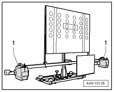
–  Attach quick-release clamps to rear wheels.
–  Attach wheel alignment sensors to rear wheels.
–  Carry out wheel rim runout compensation for rear wheels.
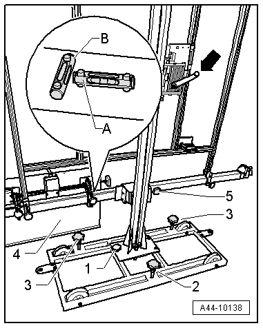
  Note
Do not take hold of the cross bar when moving the -VAS 6430-.
Adjustment procedure (irrespective of previous wheel alignment check)
  W00-10644
–  Release retainers -1- and detach air intake grille -2-.
–  Remove any dirt from sensor lens.
  A44-10150
–  If necessary, detach the mirror from the centre position and reattach it at the extreme right, next to the vertical slide.
  A44-10136
–  Position ACC setting device -VAS 6430- so that distance -A- between sensor lens and surface of reflector is 120 cm ± 5 cm.
  A44-10158
–  Attach front wheel alignment sensors -1- to -VAS 6430-.
  A44-10136
–  In area -A-, align number -2- on rotary knob with mark on reflector (number 2 on rotary knob must face vehicle).
  A44-10137
–  By moving it sideways -arrows B-, set -VAS 6430- so that laser beam coincides with centre of sensor lens in the horizontal plane.
  A44-10158
–  Use adjusting screws -1-, -2- and -3- to bring spirit levels -A- and -B- on -VAS 6430- into horizontal position.
  A44-10138
–  Using crank handle -arrow- on -VAS 6430-, set mirror -4- so that laser beam coincides with centre of sensor lens in vertical plane.
–  Set identical individual front axle toe values with fine adjustment screw -5-.
–  Difference between individual toe values must be less than 6' or equal.
  A44-10138
–  Balance out spirit levels -2- on wheel alignment sensors -1-.
–  Then check again that laser beam -3- from -VAS 6430- coincides with sensor lens.
  Note
t  -VAS 6430- is correctly aligned if the laser beam still coincides with the sensor lens at this stage, after the identical toe values have been set.
t  The alignment of -VAS 6430- must be repeated if the laser beam does not coincide with the sensor lens.
–  Connect vehicle diagnosis, testing and information system -VAS 5051 B-.
  A44-10137
–  Plug in connector of diagnosis cable -VAS 5051/5A- at diagnostic connection.
–  Switch on vehicle diagnostic, testing and information system.
The vehicle diagnostic, testing and information system is ready for operation when the selector buttons for the operating modes appear on the screen.
–  Switch on ignition.
–  Touch the Guided Fault Finding button on the display screen.
–  Select the following:
t  Make
t  Model
t  Model year
t  Version
t  Engine code letters
–  Confirm the entered information.
Wait until the vehicle diagnostic, testing and information system has interrogated all the control units in the vehicle.
–  Press the Go to button and select the option „Function/component selection“.
–  Select the relevant program in „Guided Functions“.
Then follow adjustment instructions on screen.
  A00-10303
–  For fine adjustment in „Guided Fault Finding“, use screws -2- (top) and -1- (bottom); turn adjusting tool -VAS 6190/2- in direction of arrow -A or B-
  WARNING
ACC adjustment is not completed until -VAS 5051/B- displays „Final control element diagnosis ended“.
–  Switch off ignition.
–  Detach connector of diagnosis cable -VAS 5051/5A- at diagnostic connection.
–  Disconnect battery charger → Rep. gr.27.
–  Install air intake grille → Rep. gr.63.
  A44-10143

Lane departure warning (Audi lane assist) > < Adjustment procedure using ACC setting deviceVAS 6190